Instrument Cluster / Carrier: Description and Operation
Fig. 1 Instrument Cluster:
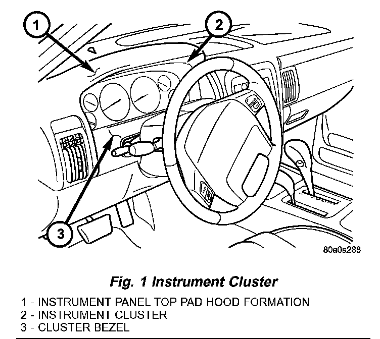
INSTRUMENT CLUSTER
The instrument cluster for this model is an ElectroMechanical Instrument Cluster (EMIC) that is located in the instrument panel above the steering column opening, directly in front of the driver. The remainder of the EMIC, including the mounts and the electrical connections, are concealed within the instrument panel behind the cluster bezel. Besides analog gauges and indicators, the EMIC module incorporates a blue-green digital Vacuum Fluorescent Display (VFD) unit for displaying odometer/trip odometer information, some warning or reminder indications and certain diagnostic information.
Fig. 2 Instrument Cluster Components:
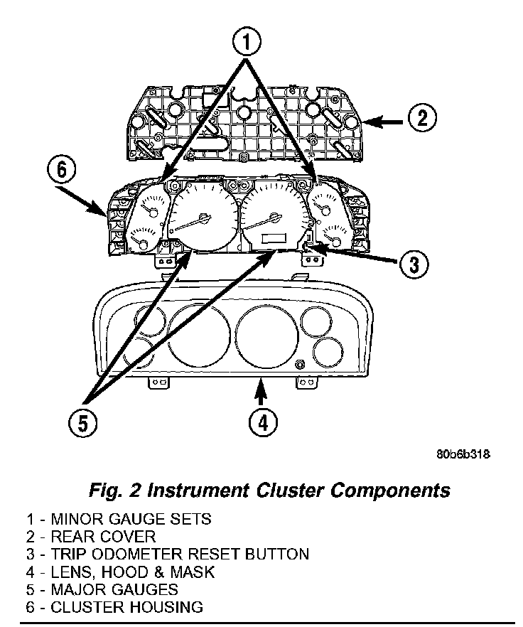
The EMIC gauges and indicators are visible through a dedicated hooded opening in the instrument panel top pad and are protected by an integral clear plastic cluster lens. Just behind and integral to the cluster lens is the cluster hood and an integral cluster mask, which are constructed of molded black plastic. Two cluster masks are used; a base version features a black matte face and no trim ring around the perimeter of each gauge opening, while a premium version features a black matte face and a raised trim ring around the perimeter of each gauge opening. The cluster hood serves as a visor and shields the face of the cluster from ambient light and reflections to reduce glare, while the cluster mask serves to separate and define the individual gauges of the EMIC. A black plastic odometer/trip odometer switch button protrudes through dedicated holes in the cluster mask and the cluster lens near the lower edge of the cluster just to the right of the speedometer. The molded plastic EMIC lens, hood and mask unit has four integral mounting tabs, two extending downward vertically from the lower edge of the unit and two extending horizontally rearward from the upper surface of the hood. The two lower mounting tabs are used to secure the EMIC to the molded plastic instrument panel cluster carrier with two screws, while the two upper tabs are secured to the underside of the hood formation of the instrument panel top pad with two screws.
The rear of the cluster housing and the EMIC electronic circuitry are protected by a molded plastic rear cover. The rear cover is secured to the cluster housing with seven screws, while the cluster lens, hood, and mask unit is secured to the cluster housing with several integral plastic latch features. The rear cover includes clearance holes for service access to each of the incandescent bulb and bulb holder units installed on the cluster circuit board for general illumination lighting and for the cluster connector receptacle. The single connector receptacle on the back of the cluster electronic circuit board connects the EMIC to the vehicle electrical system through a single dedicated take out and connector of the instrument panel wire harness.
Sandwiched between the rear cover and the lens, hood and mask unit is the cluster housing. The molded plastic cluster housing serves as the carrier for the cluster circuit board and circuitry, the cluster connector receptacle, the gauges, a Light Emitting Diode (LED) for many of the cluster indicators, the VFD unit, the cluster overlay, the gauge pointers, the odometer/trip odometer switch and the switch button. The premium cluster housing also includes an electro-luminescent lamp for general cluster illumination.
The cluster mask features two large round openings near its center through which the two major gauges are visible, and two smaller round openings stacked at the outboard side of each of the large openings through which the four minor gauges are visible. The cluster mask incorporates the cluster overlay. The cluster overlay and the dial faces of the gauges are laminated plastic units. The dark, visible, outer surface of the cluster overlay and the gauge dial faces are marked with all of the gauge graduations, but this layer is also translucent. The darkness of this outer layer prevents the cluster from appearing too cluttered or busy by concealing the cluster indicators that are not illuminated, while the translucence of this layer allows those indicators and icons that are illuminated to be readily visible.
The underlying layer of these overlays is opaque and allows light from the various indicators and illumination lamps behind it to be visible through the outer layer of the overlays only through predetermined cutouts. A rectangular opening in the gauge dial face overlay at the base of the speedometer has a smoked clear lens through which the illuminated VFD unit can be viewed. On the base instrument clusters the graphics, increments, and numerals on the gauge faces are also translucent and illuminated from behind, while the orange gauge pointers are illuminated internally. On the premium instrument clusters the graphics, increments, numerals and gauge needles are opaque while the remainder of the gauge faces are translucent and illuminated from behind by the electro-luminescent lamp.
Twelve versions of the EMIC module are offered on this model, two base and ten premium. These versions accommodate all of the variations of optional equipment and regulatory requirements for the various markets in which the vehicle will be offered. The microprocessor-based EMIC utilizes integrated circuitry and information carried on the Programmable Communications Interface (PCI) data bus network along with several hard wired analog and multiplexed inputs to monitor sensors and switches throughout the vehicle. In response to those inputs, the internal circuitry and programming of the EMIC allow it to control and integrate many electronic functions and features of the vehicle through both hard wired outputs and the transmission of electronic message outputs to other electronic modules in the vehicle over the PCI data bus.
Fig. 3 Gauges & Indicators:
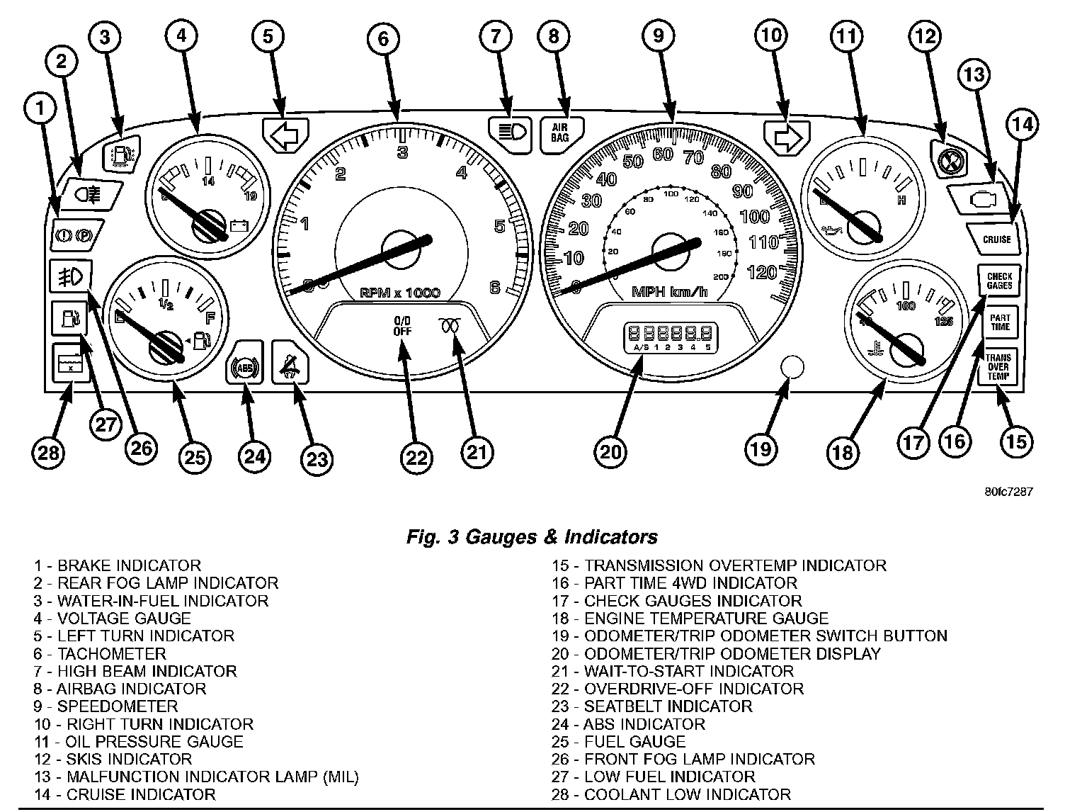
The EMIC houses six analog gauges and has provisions for up to twenty indicators. The EMIC includes the following analog gauges:
- Coolant Temperature Gauge
- Fuel Gauge
- Oil Pressure Gauge
- Speedometer
- Tachometer
- Voltage Gauge
Some of the EMIC indicators are automatically configured when the EMIC is connected to the vehicle electrical system for compatibility with certain optional equipment or equipment required for regulatory purposes in certain markets. While each EMIC may have provisions for indicators to support every available option, the configurable indicators will not be functional in a vehicle that does not have the equipment that an indicator supports.
The EMIC includes provisions for the following indicators:
- Airbag Indicator (with Airbags only)
- Antilock Brake System (ABS) Indicator
- Brake Indicator
- Check Gauges Indicator
- Coolant Low Indicator (with Diesel Engine only)
- Cruise Indicator
- Four-Wheel Drive Part Time Indicator (with Selec-Trac Transfer Case only)
- Front Fog Lamp Indicator (with Front Fog Lamps only)
- High Beam Indicator
- Low Fuel Indicator
- Malfunction Indicator Lamp (MIL)
- Overdrive-Off Indicator (except Diesel Engine)
- Rear Fog Lamp Indicator (with Rear Fog Lamps only)
- Seatbelt Indicator
- Sentry Key Immobilizer System (SKIS) Indicator
- Transmission Overtemp Indicator (except Diesel Engine)
- Turn Signal (Right and Left) Indicators
- Wait-To-Start Indicator (with Diesel Engine only)
- Water-In-Fuel Indicator (with Diesel Engine only)
Many indicators in the EMIC are illuminated by a dedicated Light Emitting Diode (LED) that is soldered onto the EMIC electronic circuit board. The LED units are not available for service replacement and, if damaged or faulty, the entire EMIC must be replaced. Base cluster illumination is accomplished by dimmable incandescent back lighting, which illuminates the gauges for visibility when the exterior lighting is turned on. Each of the incandescent bulbs is secured by an integral bulb holder to the electronic circuit board from the back of the cluster housing.
Hard wired circuitry connects the EMIC to the electrical system of the vehicle. These hard wired circuits are integral to several wire harnesses, which are routed throughout the vehicle and retained by many different methods. These circuits may be connected to each other, to the vehicle electrical system and to the EMIC through the use of a combination of soldered splices, splice block connectors, and many different types of wire harness terminal connectors and insulators. Refer to the appropriate wiring information. The wiring information includes wiring diagrams, proper wire and connector repair procedures, further details on wire harness routing and retention, as well as pin-out and location views for the various wire harness connectors, splices and grounds.
The EMIC modules for this model are serviced only as complete units. The EMIC module cannot be adjusted or repaired. If a gauge, an LED indicator, the VFD unit, the electronic circuit board, the circuit board hardware, the cluster overlay the electro-luminescent lamp (premium model only) or the EMIC housing are damaged or faulty, the entire EMIC module must be replaced. The cluster lens, hood and mask unit and the individual incandescent lamp bulbs with holders are available for individual service replacement.
The ElectroMechanical Instrument Cluster (EMIC) is designed to allow the vehicle operator to monitor the conditions of many of the vehicle components and operating systems. The gauges and indicators in the EMIC provide valuable information about the various standard and optional powertrains, fuel and emissions systems, cooling systems, lighting systems, safety systems and many other convenience items.
The EMIC is installed in the instrument panel so that all of these monitors can be easily viewed by the vehicle operator when driving, while still allowing relative ease of access for service. The microprocessor-based EMIC hardware and software uses various inputs to control the gauges and indicators visible on the face of the cluster. Some of these inputs are hard wired, but most are in the form of electronic messages that are transmitted by other electronic modules over the Programmable Communications Interface (PCI) data bus network.
The EMIC microprocessor smooths the input data using algorithms to provide gauge readings that are accurate, stable and responsive to operating conditions. These algorithms are designed to provide gauge readings during normal operation that are consistent with customer expectations. However, when abnormal conditions exist, such as high coolant temperature, the algorithm can drive the gauge pointer to an extreme position and the microprocessor turns on the Check Gauges indicator and sends an electronic chime request message to the Body Control Module (BCM) over the PCI data bus to provide distinct visual and audible indications of a problem to the vehicle operator.
The EMIC circuitry operates on battery current received through fused B(+) fuses in the Power Distribution Center (PDC) and the Junction Block (JB) on a non-switched fused B(+) circuit, and on battery current received through a fused ignition switch output (RUN/START) fuse in the JB on a fused ignition switch output (RUN/START) circuit. This arrangement allows the EMIC to provide some features regardless of the ignition switch position, while other features will operate only with the ignition switch in the On or Start positions. The EMIC circuitry is grounded through two separate ground circuits of the instrument panel wire harness. These ground circuits receive a path to ground through take outs of the instrument panel wire harness with eyelet terminal connectors that are secured by a nut to a ground stud located on the floor panel transmission tunnel beneath the center floor console, just forward of the Airbag Control Module (ACM).
The EMIC also has a self-diagnostic actuator test capability which will test each of the PCI bus message-controlled functions of the cluster by lighting the appropriate indicators (except the airbag indicator), sweeping the gauge needles across the gauge faces from their minimum to their maximum readings, and stepping the odometer display sequentially from all zeros through all nines. The self-diagnostic actuator test can be initialized manually or by using a DRBIII scan tool. Refer to the appropriate diagnostic information. See the vehicle glove box for more information on the features, use and operation of the EMIC.
GAUGES
All gauges receive battery current through the EMIC circuitry when the ignition switch is in the On or Start positions. With the ignition switch in the Off position battery current is not supplied to any gauges, and the EMIC circuitry is programmed to move all of the gauge needles back to the low end of their respective scales. Therefore, the gauges do not accurately indicate any vehicle condition unless the ignition switch is in the On or Start positions.
All of the EMIC gauges are air core magnetic units. Two fixed electromagnetic coils are located within each gauge. These coils are wrapped at right angles to each other around a movable permanent magnet. The movable magnet is suspended within the coils on one end of a pivot shaft, while the gauge needle is attached to the other end of the shaft. One of the coils has a fixed current flowing through it to maintain a constant magnetic field strength. Current flow through the second coil changes, which causes changes in its magnetic field strength. The current flowing through the second coil is changed by the EMIC circuitry in response to messages received over the PCI data bus. The gauge needle moves as the movable permanent magnet aligns itself to the changing magnetic fields created around it by the electromagnets.
The gauges are diagnosed using the EMIC self-diagnostic actuator test. Proper testing of the PCI data bus and the electronic data bus message inputs to the EMIC that control each gauge requires the use of a DRBIII scan tool. Refer to the appropriate diagnostic information. Specific operation details for each gauge may be found elsewhere in this service information.
VACUUM-FLUORESCENT DISPLAY
The Vacuum-Fluorescent Display (VFD) unit is soldered to the EMIC electronic circuit board. The display is active with the ignition switch in the On or Start positions, and inactive when the ignition switch is in any other position. The illumination intensity of the VFD unit is controlled by the EMIC circuitry based upon electronic dimming level messages received from the BCM over the PCI data bus, and is synchronized with the illumination intensity of other VFD units in the vehicle. The BCM provides dimming level messages based upon internal programming and inputs it receives from the circuitry of the left (lighting) multi-function switch on the steering column based upon the settings of the control knob and control ring on the control stalk that have been selected by the vehicle operator.
During normal operation, the EMIC VFD unit has several display capabilities including odometer, trip odometer, and some warning or reminder indications. An odometer/trip odometer switch on the EMIC circuit board is used to control some of the display modes. This switch is actuated manually by depressing the odometer/trip odometer switch button that extends through the lower edge of the cluster lens, just right of the speedometer. Actuating this switch momentarily with the ignition switch in the On position will toggle the VFD between the odometer and trip odometer modes. Depressing the switch button for about two seconds while the VFD is in the trip odometer mode will reset the trip odometer value to zero. Holding this switch depressed while turning the ignition switch from the Off position to the On position will initiate the EMIC self-diagnostic actuator test. Refer to the appropriate diagnostic information for additional details on this VFD function. The EMIC microprocessor remembers which display mode is active when the ignition switch is turned to the Off position, and returns the VFD display to that mode when the ignition switch is turned On again.
The VFD unit is diagnosed using the EMIC self-diagnostic actuator test. Proper testing of the PCI data bus and the electronic data bus message inputs to the EMIC that control some of the VFD functions requires the use of a DRBIII scan tool. Refer to the appropriate diagnostic information. Specific operation details for the odometer, the trip odometer, and the various indicator functions of the VFD may be found elsewhere in this service information.
INDICATORS
Indicators are located in various positions within the EMIC and are all connected to the EMIC electronic circuit board. The turn signal indicators are hard wired. The brake indicator is controlled by PCI data bus messages from the Controller Antilock Brake (CAB) as well as by hard wired park brake switch and brake fluid level switch inputs to the EMIC. The Malfunction Indicator Lamp (MIL) is normally controlled by PCI data bus messages from the Powertrain Control Module (PCM); however, if the EMIC loses PCI data bus communication, the EMIC circuitry will automatically turn the MIL on until PCI data bus communication is restored. The EMIC uses PCI data bus messages from the Airbag Control Module (ACM), the BCM, the PCM, the CAB, the Sentry Key Immobilizer Module (SKIM), and the Transmission Control Module (TCM) to control all of the remaining indicators.
The various EMIC indicators are controlled by different strategies; some receive fused ignition switch output from the EMIC circuitry and have a switched ground, others are grounded through the EMIC circuitry and have a switched battery feed, while still others are completely controlled by the EMIC microprocessor based upon various hard wired and electronic message inputs. Some indicators are illuminated at a fixed intensity, while the illumination intensity of others is synchronized with that of the EMIC general illumination lamps.
In addition, certain indicators in this instrument cluster are automatically configured or self-configured. This feature allows the configurable indicators to be enabled by the EMIC circuitry for compatibility with certain optional equipment. The automatically configured or self-configured indicators remain latent in each EMIC at all times and will be active only when the EMIC receives the appropriate PCI message or hard wired inputs for the optional system or equipment.
The hard wired indicator inputs are diagnosed using conventional diagnostic methods. However, the EMIC circuitry and PCI bus message controlled indicators are diagnosed using the EMIC self-diagnostic actuator test.
Proper testing of the PCI data bus and the electronic message inputs to the EMIC that control an indicator require the use of a DRBIII scan tool. Refer to the appropriate diagnostic information. Specific details of the operation for each indicator may be found elsewhere in this service information.
CLUSTER ILLUMINATION
Two types of general cluster illumination are available in this model. Base versions of the EMIC have several incandescent illumination lamps, while premium versions of the EMIC have a single electro-luminescent lamp. Both types of lamps provide cluster back lighting whenever the exterior lighting is turned On with the control knob on the left (lighting) multi-function switch control stalk. The illumination intensity of these lamps is adjusted by the EMIC microprocessor based upon electronic dimming level messages received from the Body Control Module (BCM) over the PCI data bus. The BCM provides electronic dimming level messages to the EMIC based upon internal programming and inputs it receives when the control ring on the left (lighting) multi-function switch control stalk is rotated (down to dim, up to brighten) to one of six available minor detent positions.
The incandescent illumination lamps receive battery current at all times, while the ground for these lamps is controlled by a 12-volt Pulse Width Modulated (PWM) output of the EMIC electronic circuitry. The illumination intensity of these bulbs and of the electronic Vacuum-Fluorescent Display (VFD) unit are controlled by the instrument cluster microprocessor based upon dimming level messages received from the Body Control Module (BCM) over the PCI data bus. The BCM uses inputs from the headlamp and panel dimmer switches within the left (lighting) multi-function switch control stalk and internal programming to decide what dimming level message is required. The BCM then sends the proper dimming level messages to the EMIC over the PCI data bus.
The electro-luminescent lamp unit consists of layers of phosphor, carbon, idium tin oxide, and dielectric applied by a silk-screen process between two polyester membranes and includes a short pigtail wire and connector. The lamp pigtail wire is connected to a connector receptacle on the EMIC circuit board through a small clearance hole in the cluster housing rear cover. The EMIC electronic circuitry also uses a PWM strategy to control the illumination intensity of this lamp; however, the EMIC powers this lamp with an Alternating Current (AC) rated at 80 volts rms (root mean squared) and 415 Hertz, which excites the phosphor particles causing them to luminesce.
The BCM also has several hard wired panel lamp driver outputs and sends the proper panel lamps dimming level messages over the PCI data bus to coordinate the illumination intensity of all of the instrument panel lighting and the VFD units of other electronic modules on the PCI data bus. Vehicles equipped with the Auto Headlamps option have an automatic parade mode. In this mode, the BCM uses an input from the auto headlamp light sensor to determine the ambient light levels. If the BCM decides that the exterior lighting is turned on in the daylight, it overrides the selected panel dimmer switch signal by sending a message over the PCI data bus to illuminate all VFD units at full (daytime) intensity for improved visibility when driving during the day with the exterior lighting turned on. The automatic parade mode has no effect on the incandescent bulb illumination intensity.
The hard wired cluster illumination circuits between the left (lighting) multi-function switch and the BCM may be diagnosed using conventional diagnostic tools and methods. The electro-luminescent lamp is diagnosed using the EMIC self-diagnostic actuator test. However, proper testing of the EMIC and the electronic dimming level messages sent by the BCM over the PCI data bus requires the use of a DRBIII scan tool. Refer to the appropriate diagnostic information.
CHIME SERVICE
The EMIC is programmed to request chime service from the Body Control Module (BCM) when certain indicators are illuminated. The EMIC chime request for illumination of the low fuel indicator is a customer programmable feature. When the programmed conditions are met, the EMIC generates an electronic chime request message and sends it over the PCI data bus to the BCM. Upon receiving the proper chime request, the BCM activates an integral chime tone generator to provide the audible chime tone to the vehicle operator. Proper testing of the PCI data bus and the electronic chime request message outputs from the EMIC requires the use of a DRBIII scan tool. Refer to the appropriate diagnostic information.
INPUT AND OUTPUT CIRCUITS
Hard Wired Inputs
The hard wired inputs to the EMIC include the following:
- Body Control Module Flash Enable
- Fused B(+)
- Fused Ignition Switch Output (Run-Start)
- Left Turn Signal
- Red Brake Warning Indicator Driver
- Right Turn Signal
Refer to the appropriate wiring information for additional details.
Grounds
The EMIC receives a ground path through the following hard wired circuits:
- Ground (Two Circuits)
Refer to the appropriate wiring information for additional details.
Communication
The EMIC has provisions for the following communication circuits:
- PCI Data Bus
Refer to the appropriate wiring information for additional details.