Steering Column Support Bracket
STEERING COLUMN SUPPORT BRACKETWARNING: ON VEHICLES EQUIPPED WITH AIR-BAGS, DISABLE THE AIRBAG SYSTEM BEFORE ATTEMPTING ANY STEERING WHEEL, STEERING COLUMN, OR INSTRUMENT PANEL COMPONENT DIAGNOSIS OR SERVICE. DISCONNECT AND ISOLATE THE BATTERY NEGATIVE (GROUND) CABLE, THEN WAIT TWO MINUTES FOR THE AIRBAG SYSTEM CAPACITOR TO DISCHARGE BEFORE PERFORMING FURTHER DIAGNOSIS OR SERVICE. THIS IS THE ONLY SURE WAY TO DISABLE THE AIRBAG SYSTEM. FAILURE TO TAKE THE PROPER PRECAUTIONS COULD RESULT IN ACCIDENTAL AIR-BAG DEPLOYMENT AND POSSIBLE PERSONAL INJURY.
REMOVAL
1. Disconnect and isolate the battery negative cable.
2. Remove the instrument cluster.
3. Remove the instrument panel plenum bracket from the steering column support bracket.
4. Remove the three screws that secure the instrument panel wire harness mounting tabs to the back of the steering column support bracket.
Fig. 19:
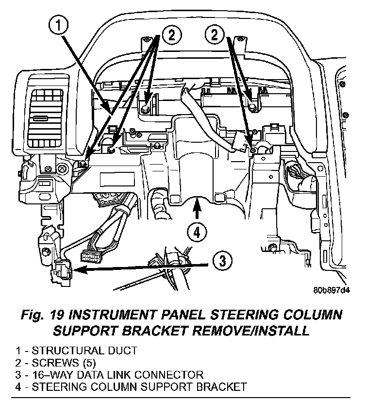
5. Remove the two screws that secure the 16-way data link connector to the instrument panel steering column support bracket and remove the connector from the bracket (Fig. 19).
6. Remove the junction block (JB) and body control module (BCM) unit from the instrument panel steering column support bracket, but do not disconnect any of the instrument panel wire harness connectors from the unit.
7. From the face of the instrument panel, remove the five screws that secure the steering column support bracket to the instrument panel structural duct.
8. Remove the steering column support bracket from the instrument panel structural duct.
INSTALLATION
1. Position the steering column support bracket to the instrument panel structural duct.
2. From the face of the instrument panel, install the five screws that secure the steering column support bracket to the instrument panel structural duct (Fig. 19), and tighten the screws to 11 N.m (8 ft. lbs.).
3. Position the instrument panel wire harness mounting tabs to the back of the steering column support bracket.
4. Install the three screws that secure the instrument panel wire harness mounting tabs to the back of the steering column support bracket.
5. Install the instrument panel plenum bracket onto the steering column support bracket.
6. Install the junction block (JB) and body control module (BCM) unit onto the instrument panel steering column support bracket.
7. Position the 16-way data link connector to the instrument panel steering column support bracket.
8. Install the two screws that secure the 16-way data link connector to the instrument panel steering column support bracket.
9. Install the instrument cluster onto the instrument panel.
10. Connect the battery negative cable.