Brakes - Front Brake Inspection RE Lawsuit BER-L-4883-04
NUMBER: 05-003-06GROUP: Brakes
DATE: July 21, 2006
OWNERS MUST PRESENT AN "INSPECTION CERTIFICATE" TO HAVE THIS BULLETIN PERFORMED OR DEALERS MAY USE VIP TO VERIFY APPLICABILITY. THIS INSPECTION OR INSPECTION AND REPAIR MUST TAKE PLACE BEFORE OCTOBER 20, 2006.
SUBJECT:
Front Brake Inspection Procedure - Class Action Lawsuit Titled "Robert Lubitz et al. vs. DaimlerChrysler Corp". Case No. BER-L-4883-04
OVERVIEW:
This bulletin provides a front brake inspection procedure.
MODELS:
2003 - 2004 (WJ) Grand Cherokee
NOTE:
This bulletin applies to vehicles bought/leased AND operated in the United States.
SPECIAL TOOLS/EQUIPMENT REQUIRED:
INSPECTION PROCEDURE:
1. While road testing the vehicle between 65 and 95 kph (40 and 60 mph), lightly apply the brakes. Document on the hard copy of the repair order whether or not there is pulsation while braking.
2. Was there a brake pulsation while braking during the test drive?
a. NO >> go to Step # 1 of Procedure A
b. YES >> go to Step # 1 of Procedure B.
PROCEDURE A
1. Raise the vehicle on a suitable hoist.
2. Remove the lug nuts from the front wheel.
3. Mark one wheel stud and corresponding wheel hole so the wheel can be reinstalled in the same relative position that it is removed from.
4. Remove front wheel and tire assembly.
5. Visually inspect the front brakes for any abnormalities and record the findings on the hard copy of the repair order.
6. Repeat steps Step # 2 - Step # 5 for the other side of the vehicle.
7. Install both front wheel and tire assemblies using the marks made in Step # 3. Torque the lug nuts in a criss-cross pattern to 14 Nm (10 ft. lbs.).
8. Lower the vehicle.
9. Using the same criss-cross pattern, final torque the lug nuts to 135 Nm (100 ft. lbs.).
10. Advise the vehicle operator of the inspection results.
PROCEDURE B
1. Drain small amount of fluid from master cylinder brake reservoir with clean suction gun.
2. Raise the vehicle on a suitable hoist.
3. Remove both front wheel and tire assemblies.
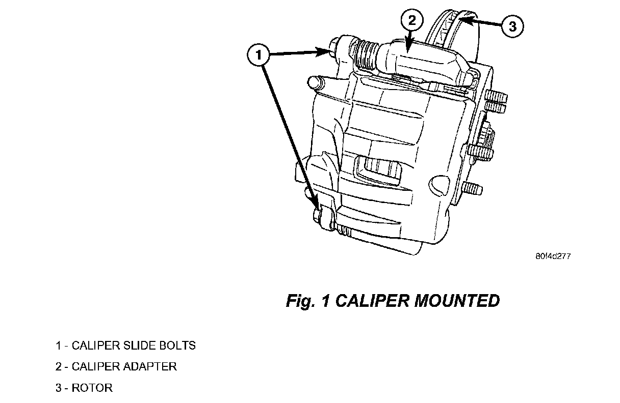
4. Bottom caliper pistons into the caliper by prying the caliper over (Fig. 1).
5. Remove the caliper slide bolts.
6. Remove the caliper from the adapter.
7. Secure the caliper assembly to nearby suspension part with a wire. Do not allow the brake hose to support the weight of the caliper.
8. Repeat Step # 4 to Step # 7 on the opposite side of the vehicle.
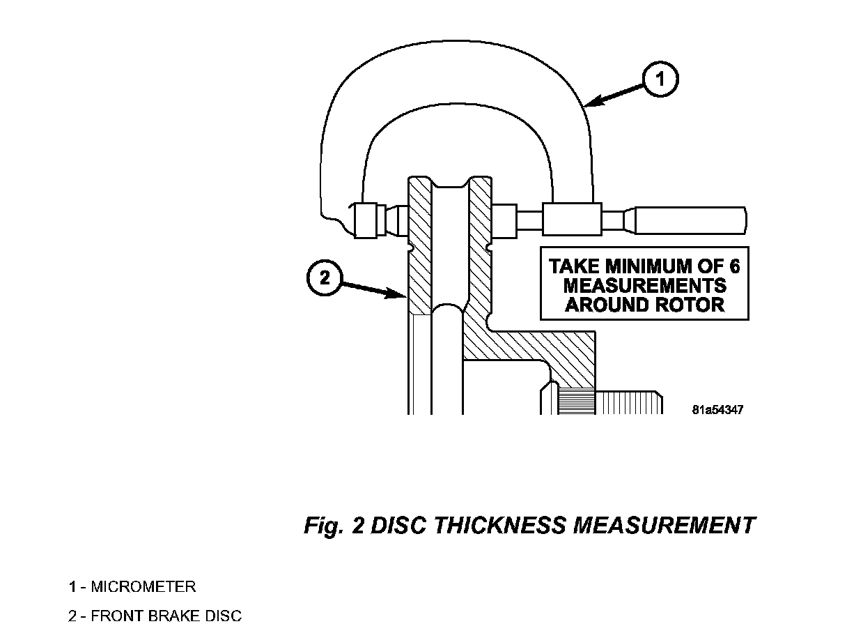
9. Measure the brake disc thickness. Minimum allowable thickness is 24.5 mm (0.9646 in.). Is there sufficient material to reface the disc(s)?
a. YES >> go to Step #10.
b. NO >> go to Step #24.
CAUTION:
For vehicles equipped with the Quadra-Drive System, consisting of the NV-247 or NV-147 transfer case and a Vari-Lok differential in the front and rear axles, the following steps must be done prior to the use of a hub mounted on-vehicle brake lathe.
10. Is the vehicle equipped with a "Quadra-Drive system?
a. YES >> go to Step # 11.
b. NO >> go to Step # 16.
11. Remove crossmember/skid plate as necessary to gain access to the propeller shaft.
12. Shift transmission and transfer case into Neutral.
13. Mark a line across the yoke at the transfer case, link yoke and propeller shaft yoke for installation reference.
14. Mark a line across the propeller shaft yoke and pinion shaft yoke for installation reference.
15. Remove the propeller shaft from the vehicle.
16. Install the lug nuts on the wheel studs and torque to 34 Nm (25 ft. lbs.) to keep the disc true and tight to the hub/bearing while the brake disc machining is in process.
NOTE:
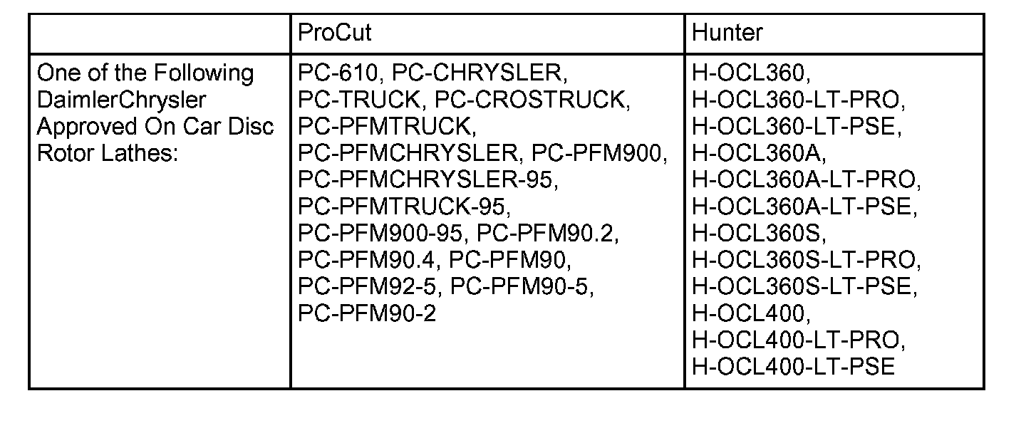
A hub mounted on-vehicle lathe is required. This type of lathe trues the disc to the vehicles hub/bearing. Refer to the SPECIAL TOOLS/EQUIPMENT REQUIRED table for a list of approved lathes.
17. Reface the front brake disc(s) with a DaimlerChrysler approved on-car brake lathe. If an on-car lathe is not available at the dealership, the disc refacing must be sublet to a facility with an approved on car lathe.
18. Install new front brake pads, p/n 05093183AB.
19. Caliper slide pins should be free from debris and lightly lubricated with brake grease, p/n J8993704.
20. Install the caliper on the adapter.
CAUTION:
Verify brake hose is not twisted or kinked.
21. Install the caliper slide pin bolts and torque to 72 Nm (53 ft. lbs.).
22. Gently lift one end of the slide pin boot to equalize air pressure, then release the boot and verify that the boot is fully covering the slide pin.
23. Repeat Step #16 to Step #22 on the opposite side of the vehicle as necessary. When front disc(s) have been refaced/replaced, proceed to Step # 35.
24. Remove and discard the old brake disc(s).
25. Thoroughly clean the surface of the wheel hub/bearing assembly where it mates to the brake disc. The hub surface must be free of corrosion and dirt so that the new brake disc rests flush against the hub. This important step will prevent excess disc lateral runout.
26. Inspect the new brake disc and its mating surface with the hub/bearing assembly. Install the new brake disc, p/n 52098672, to the hub/bearing assembly. Install the lug nuts on the wheel studs and torque to 34 Nm (25 ft. lbs.) to keep the disc true and tight to the hub/bearing.
NOTE:
Use a dial indicator to insure that minimum lateral runout is achieved for each disc.
27. Using a dial indicator determine the brake disc lateral runout. If the runout exceeds 0.025 mm (0.001 in.), match mount the brake disc to the hub/bearing assembly until the minimum lateral runout for the new brake disc and hub/bearing assembly combination is obtained.
28. Verify that the maximum allowable lateral runout of the brake disc and hub/bearing assembly combination does not exceed 0.025 mm (0.001 in.). If the lateral runout is in excess of specification, then the cause must be determined and corrected before proceeding further with this repair.
29. Install new front brake pads, p/n 05093183AB.
30. Caliper slide pins should be free from debris and lightly lubricated with brake grease, p/n J8993704
31. Install the caliper on the adapter.
CAUTION:
Verify brake hose is not twisted or kinked.
32. Install the caliper slide pin bolts and torque to 72 Nm (53 ft. lbs.).
33. Gently lift one end of the slide pin boot to equalize air pressure, then release the boot and verify that the boot is fully covering the slide pin.
34. Repeat Step #24 to Step #33 on the opposite side of the vehicle as necessary. When both front discs have been refaced/replaced, proceed to Step # 40.
35. Was the propeller shaft removed from the vehicle earlier?
a. Yes >> go to Step # 36
b. No >> go to Step # 40.
36. Position front propeller shaft under vehicle with rear universal joint over the transfer case yoke.
37. Align the front of the propeller shaft to the axle pinion yoke using the reference marks made previously.
38. Align the rear of the propeller shaft to the transfer case yoke using the reference marks made previously.
39. What style propeller shaft is the vehicle equipped with?
a. If propeller shaft is Universal joint style, torque the U-joint strap/clamp bolts at the axle yoke to 19 Nm (14 ft. lbs.). Tighten the universal joint to transfer case bolts to 27 Nm (20 ft. lbs.). Proceed to Step # 40.
b. If propeller shaft is CV joint style, install bolts to the front C/V joint and torque bolts to 32 Nm (24 ft. lbs.). Install the bolts to the rear C/V joint and torque bolts to 32 Nm (24 ft. lbs.). Proceed to Step # 40.
40. Install both front wheel and tire assemblies. Tighten the front lug nuts to 135 Nm (100 ft. lbs.). This important step helps to prevent warping of the brake discs.
41. Lower the vehicle.
42. Pump the brake pedal to insure that the front caliper brake pads are seated to the brake discs. Verify correct brake fluid level. Check brake system operation.
POLICY:
Refer to Warranty Bulletin D-06-17, available in TechCONNECT under:
efiles>Service>Warranty>CDJ Bulletins, for instructions detailing administration of this service action.
TIME ALLOWANCE:

FAILURE CODE:
Disclaimer:
This bulletin is supplied as technical information only and is not an authorization for repair.