Glove Box
GLOVE BOXSTANDARD PROCEDURE - GLOVE BOX ROLL DOWN
WARNING: ON VEHICLES EQUIPPED WITH AIRBAGS, DISABLE THE AIRBAG SYSTEM BEFORE ATTEMPTING ANY STEERING WHEEL, STEERING COLUMN, OR INSTRUMENT PANEL COMPONENT DIAGNOSIS OR SERVICE. DISCONNECT AND ISOLATE THE BATTERY NEGATIVE (GROUND) CABLE, THEN WAIT TWO MINUTES FOR THE AIRBAG SYSTEM CAPACITOR TO DISCHARGE BEFORE PERFORMING FURTHER DIAGNOSIS OR SERVICE. THIS IS THE ONLY SURE WAY TO DISABLE THE AIRBAG SYSTEM. FAILURE TO TAKE THE PROPER PRECAUTIONS COULD RESULT IN ACCIDENTAL AIRBAG DEPLOYMENT AND POSSIBLE PERSONAL INJURY.
1. Disconnect and isolate the battery negative cable.
2. Open the glove box until the integral stops on the back edge of the glove box bin are resting against the rubber stop bumpers in the upper glove box opening reinforcement.
3. Reach into the glove box and with the middle finger of each hand, deflect the rubber flap of the two glove box stop bumpers on the upper glove box opening reinforcement toward the front of the vehicle.
Fig. 2:
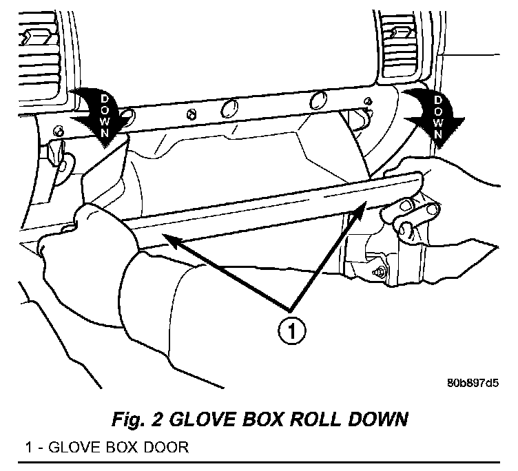
4. With the glove box stop bumpers deflected, roll the glove box door downward until the integral stops on the back edge of the glove box bin pass through the rubber stop bumper openings in the upper glove box opening reinforcement (Fig. 2)
5. Before rolling the glove box back up into the instrument panel, grasp the pneumatic glove box damper arm and pull the connector feature rearward to the end of its travel. The rubber stop bumpers will be deflected automatically by the integral stops on the back of the glove box when the glove box is rolled back up into the instrument panel.
6. With the glove box stops oriented behind the stop bumpers, position the connector feature of the damper to the keyed slot on the outboard end of the glove box bin.
7. Using hand pressure, press downward on the damper arm until the damper connector feature snaps back into the keyed slot.
REMOVAL
WARNING: ON VEHICLES EQUIPPED WITH AIRBAGS, DISABLE THE AIRBAG SYSTEM BEFORE ATTEMPTING ANY STEERING WHEEL, STEERING COLUMN, OR INSTRUMENT PANEL COMPONENT DIAGNOSIS OR SERVICE. DISCONNECT AND ISOLATE THE BATTERY NEGATIVE (GROUND) CABLE, THEN WAIT TWO MINUTES FOR THE AIRBAG SYSTEM CAPACITOR TO DISCHARGE BEFORE PERFORMING FURTHER DIAGNOSIS OR SERVICE. THIS IS THE ONLY SURE WAY TO DISABLE THE AIRBAG SYSTEM. FAILURE TO TAKE THE PROPER PRECAUTIONS COULD RESULT IN ACCIDENTAL AIRBAG DEPLOYMENT AND POSSIBLE PERSONAL INJURY.
1. Disconnect and isolate the battery negative cable.
2. Roll the glove box down from the instrument panel.
NOTE: Be certain to use care not to damage or remove the glove box hinge bumpers on the lower instrument panel glove box opening reinforcement when removing the glove box from the instrument panel.
Fig. 3:
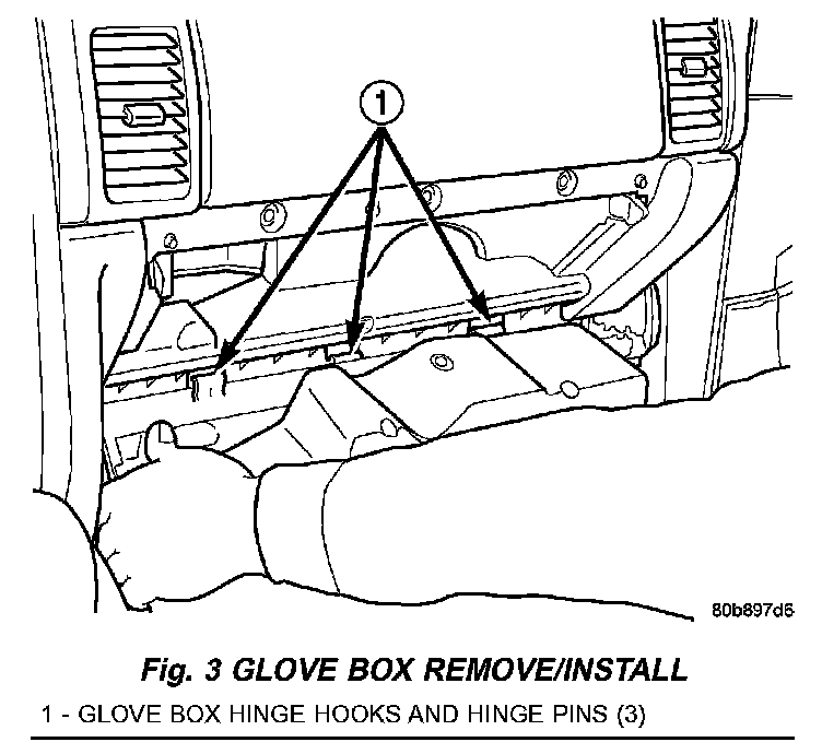
3. Firmly grip both ends of the glove box door, then twist and pull the door as necessary to disengage the inboard hinge hook from the inboard hinge pin on the instrument panel and reorient the hook to the underside of the hinge pin (Fig. 3).
4 .Raise the glove box door until it is perpendicular to the instrument panel.
5. Twist the door slightly in the counterclockwise direction and use a jiggling action to disengage the remaining two hinge hooks from their respective hinge pins on the instrument panel.
6. Remove the glove box from the instrument panel.
INSTALLATION
WARNING: ON VEHICLES EQUIPPED WITH AIR-BAGS, DISABLE THE AIRBAG SYSTEM BEFORE ATTEMPTING ANY STEERING WHEEL, STEERING COLUMN, OR INSTRUMENT PANEL COMPONENT DIAGNOSIS OR SERVICE. DISCONNECT AND ISOLATE THE BATTERY NEGATIVE (GROUND) CABLE, THEN WAIT TWO MINUTES FOR THE AIRBAG SYSTEM CAPACITOR TO DISCHARGE BEFORE PERFORMING FURTHER DIAGNOSIS OR SERVICE. THIS IS THE ONLY SURE WAY TO DISABLE THE AIRBAG SYSTEM. FAILURE TO TAKE THE PROPER PRECAUTIONS COULD RESULT IN ACCIDENTAL AIR-BAG DEPLOYMENT AND POSSIBLE PERSONAL INJURY.
NOTE: Be certain to use care not to damage or remove the glove box hinge bumpers on the lower instrument panel glove box opening reinforcement when installing the glove box onto the instrument panel.
Fig. 3:
1. Position the glove box to the instrument panel with the outboard hinge hook oriented over the outboard hinge pin and the center hinge hook oriented under the center hinge pin (Fig. 3).
2. Raise the glove box door until it is perpendicular to the instrument panel.
3. Firmly grip both ends of the glove box door and twist the door slightly in the clockwise direction to engage the inboard glove box hinge hook over the inboard hinge pin on the instrument panel.
4. Roll the glove box back up into the instrument panel.
5. Connect the battery negative cable.