Glove Box Latch Striker Replacement
GLOVE BOX LATCH STRIKERREMOVAL
WARNING: ON VEHICLES EQUIPPED WITH AIR-BAGS, DISABLE THE AIRBAG SYSTEM BEFORE ATTEMPTING ANY STEERING WHEEL, STEERING COLUMN, OR INSTRUMENT PANEL COMPONENT DIAGNOSIS OR SERVICE. DISCONNECT AND ISOLATE THE BATTERY NEGATIVE (GROUND) CABLE, THEN WAIT TWO MINUTES FOR THE AIRBAG SYSTEM CAPACITOR TO DISCHARGE BEFORE PERFORMING FURTHER DIAGNOSIS OR SERVICE. THIS IS THE ONLY SURE WAY TO DISABLE THE AIRBAG SYSTEM. FAILURE TO TAKE THE PROPER PRECAUTIONS COULD RESULT IN ACCIDENTAL AIR-BAG DEPLOYMENT AND POSSIBLE PERSONAL INJURY.
1. Disconnect and isolate the battery negative cable.
2. If the inboard glove box latch striker is being serviced, remove the lower right center bezel from the instrument panel. If the outboard glove box latch striker is being serviced, remove the end cap from the instrument panel.
Fig. 5:
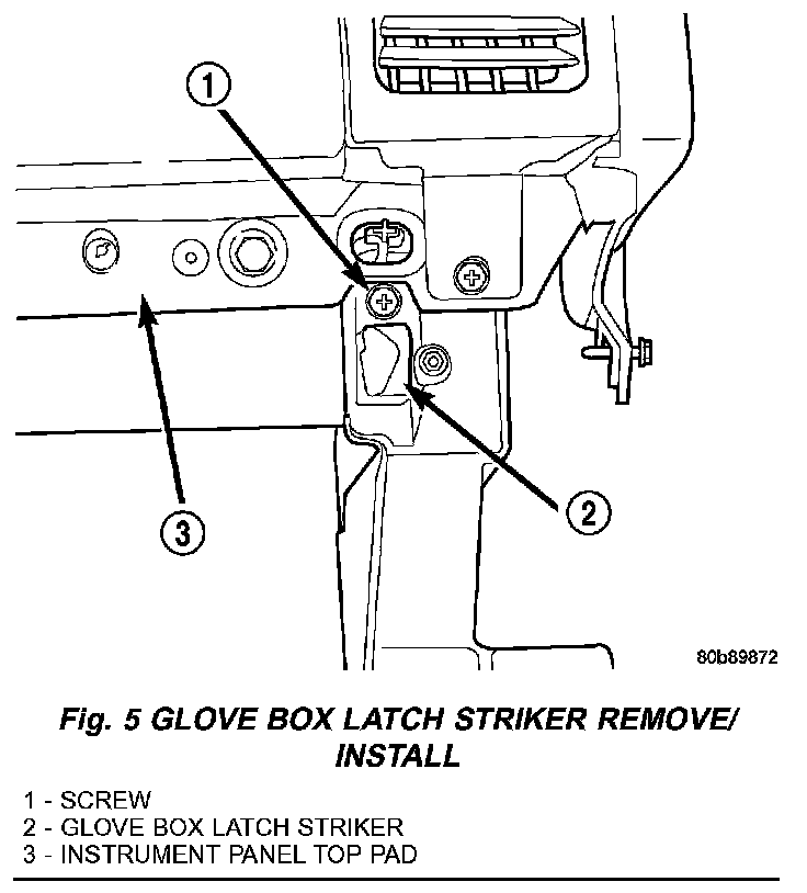
3. Remove the one screw that secures the upper mounting flange of the glove box latch striker to the instrument panel structural duct at either side of the glove box opening (Fig. 5).
4. Pull the upper mounting flange of the glove box latch striker downward to disengage the hook formation on the lower end of the striker from the mounting hole in the instrument panel structural duct.
5. Remove the glove box latch striker from the instrument panel.
INSTALLATION
WARNING: ON VEHICLES EQUIPPED WITH AIR-BAGS, DISABLE THE AIRBAG SYSTEM BEFORE ATTEMPTING ANY STEERING WHEEL, STEERING COLUMN, OR INSTRUMENT PANEL COMPONENT DIAGNOSIS OR SERVICE. DISCONNECT AND ISOLATE THE BATTERY NEGATIVE (GROUND) CABLE, THEN WAIT TWO MINUTES FOR THE AIRBAG SYSTEM CAPACITOR TO DISCHARGE BEFORE PERFORMING FURTHER DIAGNOSIS OR SERVICE. THIS IS THE ONLY SURE WAY TO DISABLE THE AIRBAG SYSTEM. FAILURE TO TAKE THE PROPER PRECAUTIONS COULD RESULT IN ACCIDENTAL AIR-BAG DEPLOYMENT AND POSSIBLE PERSONAL INJURY.
1. Position the glove box latch striker to the instrument panel.
2. Engage the hook formation on the lower end of the glove box latch striker in the mounting hole in the instrument panel structural duct.
3. Roll the upper mounting flange of the glove box latch striker upward until it is flush with the instrument panel structural duct on either side of the glove box opening.
Fig. 5:
4. Install and tighten the screw that secures the upper mounting flange of the glove box latch striker to the instrument panel structural duct (Fig. 5).
5. If the inboard glove box latch striker was serviced, reinstall the lower right center bezel onto the instrument panel. If the outboard glove box latch striker was serviced, reinstall the end cap onto the instrument panel.
6. Connect the battery negative cable.