Instrument Panel Top Pad Assembly
INSTRUMENT PANEL TOP PADREMOVAL
WARNING: ON VEHICLES EQUIPPED WITH AIR-BAGS, DISABLE THE AIRBAG SYSTEM BEFORE ATTEMPTING ANY STEERING WHEEL, STEERING COLUMN, OR INSTRUMENT PANEL COMPONENT DIAGNOSIS OR SERVICE. DISCONNECT AND ISOLATE THE BATTERY NEGATIVE (GROUND) CABLE, THEN WAIT TWO MINUTES FOR THE AIRBAG SYSTEM CAPACITOR TO DISCHARGE BEFORE PERFORMING FURTHER DIAGNOSIS OR SERVICE. THIS IS THE ONLY SURE WAY TO DISABLE THE AIRBAG SYSTEM. FAILURE TO TAKE THE PROPER PRECAUTIONS COULD RESULT IN ACCIDENTAL AIR-BAG DEPLOYMENT AND POSSIBLE PERSONAL INJURY.
1. Disconnect and isolate the battery negative cable.
2. Remove the trim from the right and left A-pillars.
3. Remove the top cover from the instrument panel.
Fig. 8:
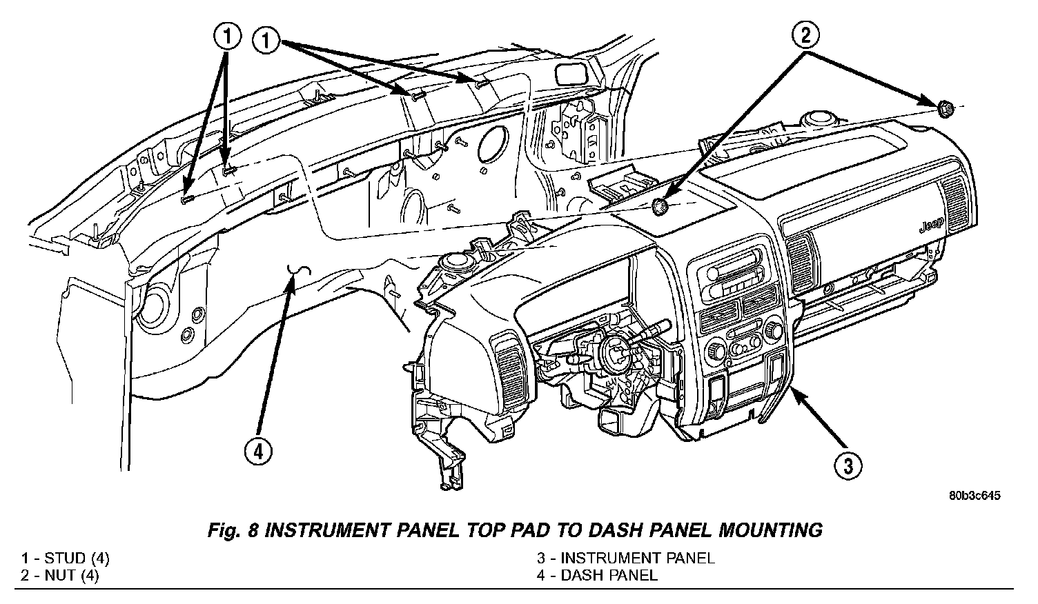
4. Remove the four nuts that secure the instrument panel top pad to the studs on the dash panel near the windshield fence line (Fig. 8).
5. Remove the speakers from the instrument panel top pad.
6. Disengage the retainer that secures each of the two instrument panel wire harness speaker take outs to the mounting hole in the instrument panel top pad. Tuck the loose ends of these speaker take outs down the defroster ducts to keep them out of the way during the remainder of this procedure.
7. If equipped, remove the two screws that secure the automatic headlamp light sensor/vehicle theft security system indicator unit to the instrument panel top pad just outboard of the driver side defroster outlet. Move the sensor/indicator unit towards the windshield to keep it out of the way during the remainder of this procedure.
8. Remove the cluster bezel.
9. Remove the instrument cluster.
10. Remove the steering column opening cover.
11. Roll the glove box down.
12. Remove the end cap from the passenger side lower outboard end of the instrument panel.
13. Remove the lower right center bezel.
14. Remove the glove box lamp and switch.
Fig. 9:
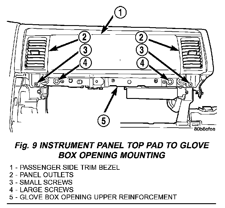
15. Remove the two large screws on the glove box opening upper reinforcement that secure the top pad to the instrument panel structural duct (Fig. 9).
16. Remove the two small screws on the glove box opening upper reinforcement that secure the panel outlets to the instrument panel structural duct.
17. Remove the center upper bezel.
18. Remove the center lower bezel.
19. Remove the four screws that secure the radio to the instrument panel structural duct. Pull the radio out of the instrument panel only far enough to access the screws that secure the top pad to the instrument panel structural duct.
20. Remove the four screws that secure the heater-A/C control to the instrument panel structural duct. Pull the heater-A/C control out of the instrument panel only far enough to access the screws that secure the top pad to the instrument panel structural duct.
21. Remove all of the screws that secure the perimeter of the top pad to the instrument panel structural duct.
22. Remove the front bin from the floor console.
23. Reach through the front bin opening of the floor console to access and remove the two screws that secure the center floor tunnel bracket to the instrument panel.
24. Reach through the front bin opening of the floor console to access and loosen the two nuts that secure the center floor tunnel bracket to the studs on the floor panel transmission tunnel.
Fig. 10:
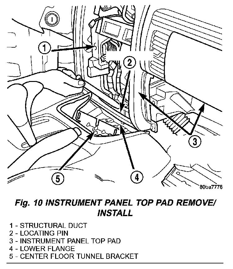
25. Slide the center floor tunnel bracket rearward in the vehicle far enough to disengage the locating hole in the lower flange of the top pad from the locating pin on the instrument panel structural duct (Fig. 10).
26. Remove the instrument panel top pad from the instrument panel structural duct.
INSTALLATION
WARNING: ON VEHICLES EQUIPPED WITH AIR-BAGS, DISABLE THE AIRBAG SYSTEM BEFORE ATTEMPTING ANY STEERING WHEEL, STEERING COLUMN, OR INSTRUMENT PANEL COMPONENT DIAGNOSIS OR SERVICE. DISCONNECT AND ISOLATE THE BATTERY NEGATIVE (GROUND) CABLE, THEN WAIT TWO MINUTES FOR THE AIRBAG SYSTEM CAPACITOR TO DISCHARGE BEFORE PERFORMING FURTHER DIAGNOSIS OR SERVICE. THIS IS THE ONLY SURE WAY TO DISABLE THE AIRBAG SYSTEM. FAILURE TO TAKE THE PROPER PRECAUTIONS COULD RESULT IN ACCIDENTAL AIR-BAG DEPLOYMENT AND POSSIBLE PERSONAL INJURY.
If the top pad is being replaced with a new unit, be certain to transfer or install the panel outlets and the passenger side trim bezel to the new unit before it is installed on the instrument panel structural duct.
1. Position the instrument panel top pad over the instrument panel structural duct and the studs on the dash panel near the windshield fence line.
2. Route the instrument panel wire harness take out for the glove box lamp and switch unit to the switch mounting hole in the upper glove box opening reinforcement.
Fig. 10:
3. Reach through the front bin opening of the floor console to engage the locating hole in the lower flange of the top pad with the locating pin on the instrument panel structural duct (Fig. 10).
4. Reach through the front bin opening of the floor console to slide the center floor tunnel bracket forward in the vehicle far enough to capture the lower flange of the top pad between the bracket and the structural duct.
5. Reach through the front bin opening of the floor console to install the two screws that secure the center floor tunnel bracket to the instrument panel and tighten to 11 N.m (8 ft. lbs.).
6. Reach through the front bin opening of the floor console to install the two nuts that secure the center floor tunnel bracket to the studs on the floor panel transmission tunnel and tighten to 11 N.m (8 ft. lbs.).
7. Install the front bin into the floor console.
8. Install all of the screws that secure the perimeter of the top pad to the instrument panel structural duct.
9. Install the four screws that secure the heater-A/C control to the instrument panel structural duct.
10. Install the four screws that secure the radio to the instrument panel structural duct.
11. Install the center lower bezel.
12. Install the center upper bezel.
Fig. 9:
13. Install the two large screws on the glove box opening upper reinforcement that secure the top pad to the instrument panel structural duct (Fig. 9) and tighten to 11 N.m (8 ft. lbs.).
14. Install the two small screws on the glove box opening upper reinforcement that secure the panel outlets to the instrument panel structural duct.
15. Install the glove box lamp and switch.
16. Install the lower right center bezel.
17. Install the end cap.
18. Roll the glove box back up.
19. Install the steering column opening cover.
20. Install the instrument cluster.
21. Install the cluster bezel onto the instrument panel.
22. If equipped, position the automatic headlamp light sensor/vehicle theft security system indicator unit to the instrument panel top pad just outboard of the driver side defroster outlet. Install and tighten the two screws that secure the sensor/indicator unit.
23. Engage the retainer that secures each of the two instrument panel wire harness speaker take outs to the mounting hole in the instrument panel top pad.
24. Install the speakers onto the instrument panel top pad.
Fig. 8:
25. Install the four nuts that secure the instrument panel top pad to the studs on the dash panel near the windshield fence line (Fig. 8), and tighten the nuts to 11 N.m (8 ft. lbs.).
26. Install the top cover onto the instrument panel.
27. Install the trim onto the right and left A-pillars.
28. Reconnect the battery negative cable.