Instrument Cluster Preliminary Diagnosis
- If indicator lights operate, but all gauges are inoperative, go to next step. If all gauges and Programmable Communication Interface (PCI) bus indicator lights are inoperative, go to step 5
.
- Remove and inspect fuse No. 24 (10-amp) in Power Distribution Center (PDC). PDC is located in engine compartment, near battery. If fuse is okay, go to next step. If fuse is blown, locate and repair cause of blown fuse. See WIRING DIAGRAMS
. Install new fuse and recheck system operation.
- Measure voltage between ground and power side of fuse No. 24. If battery voltage is present, go to next step. If battery voltage is not present, locate and repair open circuit between battery and PDC. See WIRING DIAGRAMS
.
- Disconnect negative battery cable. Remove instrument cluster. See INSTRUMENT CLUSTER
under REMOVAL & INSTALLATION. Reconnect negative battery cable. Using DVOM, check for battery voltage between ground and instrument cluster connector C1 terminal No. 8 (Pink/White wire). See Fig 1
. If battery voltage is present, reinstall instrument cluster and perform actuator test. Go to VACUUM FLUORESCENT DISPLAY SELF-DIAGNOSTIC ACTUATOR TEST
. If battery voltage is not present, repair open in Pink/White wire between fuse No. 24 in PDC and instrument cluster. See WIRING DIAGRAMS
.
- Remove and inspect fuse No. 10 (10-amp) in fuse box, located behind glove box. If fuse is okay, go to next step. If fuse is blown, locate and repair cause of blown fuse. See WIRING DIAGRAMS
. Install new fuse and recheck system operation.
- Turn ignition on. Measure voltage between ground and power side of fuse No. 10. If battery voltage is present, go to next step. If battery voltage is not present, locate and repair open circuit between ignition switch and fuse box. See WIRING DIAGRAMS
.
- Turn ignition off. Disconnect negative battery cable. Install instrument cluster. Reconnect negative battery cable. Turn ignition on. Set parking brake and observe instrument cluster BRAKE warning light. If BRAKE warning light illuminates, go to next step. If BRAKE warning light does not illuminate, go to step 9
.
- Turn ignition off. Turn parking lights on and adjust instrument panel lights dimmer rheostat to full bright position. If instrument panel lights are on, perform actuator test. Go to VACUUM FLUORESCENT DISPLAY SELF-DIAGNOSTIC ACTUATOR TEST
. If instrument panel lights are off, go to step 10
.
- Turn ignition off. Disconnect negative battery cable. Remove instrument cluster. Reconnect negative battery cable. Turn ignition on. Using DVOM, check for battery voltage between ground and instrument cluster connector C1 terminal No. 7 (Dark Blue/White wire). See Fig 1
. If battery voltage is present, perform actuator test. Go to VACUUM FLUORESCENT DISPLAY SELF-DIAGNOSTIC ACTUATOR TEST
. If battery voltage is not present, locate and repair open in Dark Blue/White wire between instrument cluster and fuse block. See WIRING DIAGRAMS
.
- Disconnect negative battery cable. Remove instrument cluster. Check continuity between ground and instrument cluster connector C1 terminal No. 5 (Black/Light Green wire). See Fig 1
. If continuity is present, perform actuator test. Go to VACUUM FLUORESCENT DISPLAY SELF-DIAGNOSTIC ACTUATOR TEST
. If continuity is not present, locate and repair open in Black/Light Green wire between instrument cluster and ground. See WIRING DIAGRAMS
.
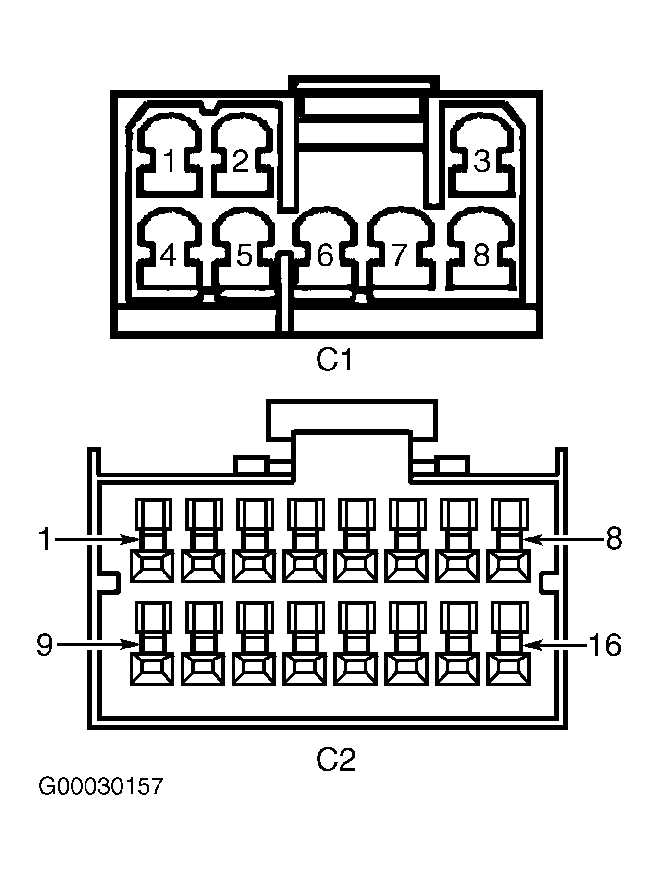 Courtesy of DAIMLERCHRYSLER CORPORATION