Indicator Fails To Illuminate During Bulb Check
- Remove and inspect fuse No. 1 (20-amp) in fuse box, located behind glove box. If fuse is okay, go to next step. If fuse is blown, locate and repair cause of blown fuse. See POWER DISTRIBUTION
in SYSTEM WIRING DIAGRAMS article in ELECTRICAL. Install new fuse and recheck system operation.
- Using DVOM, check for battery voltage between ground and power side of fuse No. 1. If battery voltage is present, go to next step. If battery voltage is not present, locate and repair open circuit between battery and fuse box.
- Remove and inspect fuse No. 12 (10-amp) in fuse box. If fuse is okay, go to next step. If fuse is blown, locate and repair cause of blown fuse. See POWER DISTRIBUTION
in SYSTEM WIRING DIAGRAMS article in ELECTRICAL. Install new fuse and recheck system operation.
- Turn ignition on. Using DVOM, check for battery voltage between ground and power side of fuse No. 12. If battery voltage is present, go to next step. If battery voltage is not present, locate and repair open circuit between ignition switch and fuse box. See ANTI-THEFT
in SYSTEM WIRING DIAGRAMS article in ELECTRICAL.
- Turn ignition off. Disconnect negative battery cable. Locate and disconnect Sentry Key Immobilizer Module (SKIM) and disconnect electrical connector. See Fig 1
. Using DVOM, check for continuity between ground and SKIM connector terminals No. 2 (Black/Light Blue wire) and No. 5 (Black wire). See Fig 2
. If continuity is indicated, go to next step. If continuity is not indicated, repair open in Black/Light Blue or Black wire between SKIM and ground. See ANTI-THEFT
in SYSTEM WIRING DIAGRAMS article in ELECTRICAL.
- Reconnect negative battery cable. Using DVOM, check for battery voltage between ground and SKIM connector terminal No. 6 (Pink/Red wire). If battery voltage is indicated, go to next step. If battery voltage is not indicated, repair open in Pink/Red wire between SKIM and fuse box. See ANTI-THEFT
in SYSTEM WIRING DIAGRAMS article in ELECTRICAL.
- Turn ignition on. Using DVOM, check for battery voltage between ground and SKIM connector terminal No. 4 (Dark Blue wire). If battery voltage is indicated, diagnose SKIM using scan tool. See appropriate ANTI-THEFT SYSTEMS article for diagnostic information. If battery voltage is not indicated, repair open in Dark Blue wire between SKIM and fuse box. See ANTI-THEFT
in SYSTEM WIRING DIAGRAMS article in ELECTRICAL.
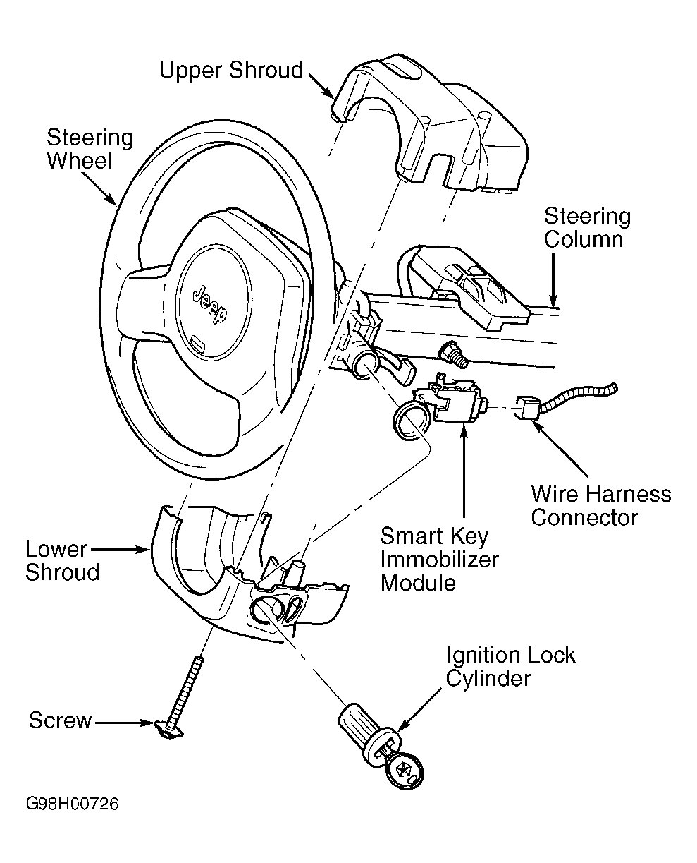 Courtesy of CHRYSLER CORP.
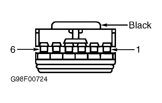 Courtesy of CHRYSLER CORP.