Part 5 of 5
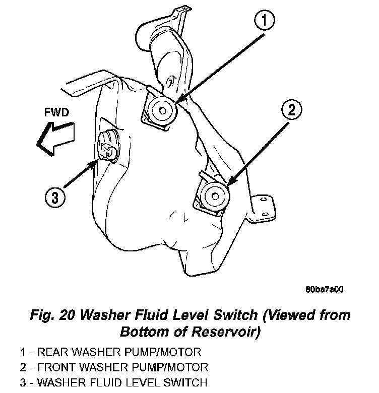
Fig.20 Washer Fluid Level Switch (Viewed From Bottom Of Reservoir):
WASHER FLUID LEVEL SWITCH
The washer fluid level switch is a single pole, single throw reed-type switch mounted near the front of the washer reservoir, forward of the two washer pump/motors. Only the molded plastic switch mounting flange and connector receptacle are visible when the switch is installed in the reservoir.
A short nipple formation extends from the inner surface of the switch mounting flange, and a barb on the nipple near the switch mounting flange is press-fit into a rubber grommet seal installed in the mounting hole of the reservoir. A small plastic float pivots on the end of a bracket that extends from the switch nipple formation. Within the float is a small magnet, which actuates the reed switch. The washer fluid level switch cannot be adjusted or repaired. If faulty or damaged, the switch must be replaced.
The washer fluid level switch uses a pivoting, oblong float to monitor the level of the washer fluid in the washer reservoir. The float contains a small magnet. When the float pivots, the changing proximity of its magnetic field will cause the contacts of the small, stationary reed switch to open or close. When the fluid level in the washer reservoir is at or above the float level, the float moves to a vertical position and the switch contacts open. When the fluid level in the washer reservoir falls below the pivoting float, the float moves to a horizontal position and the switch contacts close. The switch is connected to the vehicle electrical system through a dedicated take out and connector of the left headlamp and dash wire harness. The switch receives a five volt reference signal from the Body Control Module (BCM) through the washer fluid switch output circuit. The switch is grounded at all times through another take out of the left headlamp and dash wire harness with a single eyelet terminal connector that is secured under a ground screw near the top of the left front fender inner shield in the engine compartment.
When the switch closes, the BCM senses the voltage change on the circuit. The BCM is programmed to send low washer fluid messages to the Electronic Vehicle Information Center (EVIC) over the Programmable Communications Interface (PCI) data bus. The EVIC is programmed to respond to this message by displaying the Washer Fluid Low warning and sending a chime request message back to the BCM over the PCI data bus. Then the BCM generates an audible chime tone warning. A resistor within the washer fluid level switch allows the BCM to monitor and diagnose this circuit. The BCM will store a Diagnostic Trouble Code (DTC) for any fault that it detects. For retrieval of this fault information and further diagnosis of the washer fluid level switch, the BCM, the EVIC, the PCI data bus, the BCM message outputs to the EVIC that control the Low Washer Fluid indicator, or the EVIC message outputs to the BCM that control chime service, a DRB III scan tool and the appropriate diagnostic information are required.
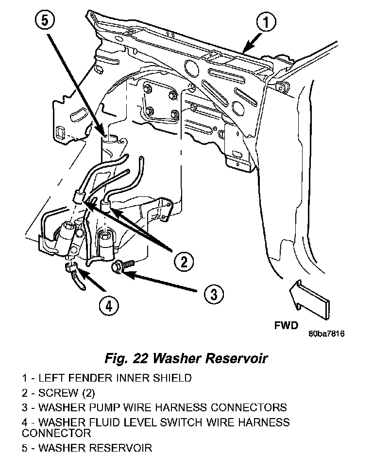
Fig.22 Washer Reservoir:
WASHER RESERVOIR
A single washer fluid reservoir is used for both the front and rear washer systems. The molded plastic washer fluid reservoir is concealed between the left front inner and outer fender panels, behind the inner fender liner in front of the left front wheel. The only visible component of the washer reservoir is the filler neck and cap unit, which extends through a hole in the left front wheel house extension panel into the engine compartment. A bright yellow plastic filler cap with a rubber seal and an International Control and Display Symbol icon for "Windshield Washer" and the text "Washer Fluid Only" molded into it snaps over the open end of the filler neck. The cap hinges on and is secured to a molded-in hook formation on the rear of the reservoir filler neck.
There are separate, dedicated holes on the outboard side of the reservoir provided for the mounting of the front and rear washer/pump motor units, and another dedicated hole on the front of the reservoir for the washer fluid level switch. The inboard side of the washer reservoir has an integral flange that is secured to the inside of the left front fender wheel house by two screws, while an integral molded tab engages a slot in the left front fender inner shield to support the outboard side of the reservoir. Another screw secures the reservoir filler neck to the left front fender inner shield near the front of the engine compartment. The left front fender wheel house inner liner must be removed to access the washer reservoir for service.
The washer reservoir cannot be repaired and, if faulty or damaged, it must be replaced. The washer reservoir, the grommet seals for the washer pump/ motor units and the washer fluid level switch, and the filler cap are each available for service replacement.
The washer fluid reservoir provides a secure, on-vehicle storage location for a large reserve of washer fluid for operation of the front and rear washer systems. The washer reservoir filler neck provides a clearly marked and readily accessible point from which to add washer fluid to the reservoir. The front and rear washer/pump motor units are located in a sump area near the front of the reservoir to be certain that washer fluid will be available to the pumps as the fluid level in the reservoir becomes depleted. The front washer pump/motor unit is mounted in the lowest position in the sump so that the front washers will operate even after the rear washer system will no longer operate. The washer fluid level switch is mounted just above the sump area of the reservoir so that there will be adequate warning to the vehicle operator that the washer fluid level is low, before the washer system will no longer operate.
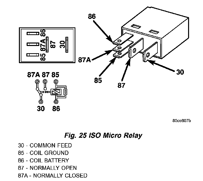
Fig.25 ISO Micro Relay:
WIPER HIGH/LOW RELAY
The wiper high/low relay is located in the Power Distribution Center (PDC) in the engine compartment near the battery. The wiper high/low relay is a conventional International Standards Organization (ISO) micro relay. Relays conforming to the ISO specifications have common physical dimensions, current capacities, terminal patterns, and terminal functions. The relay is contained within a small, rectangular, molded plastic housing and is connected to all of the required inputs and outputs by five integral male spade-type terminals that extend from the bottom of the relay base.
The wiper high/low relay cannot be adjusted or repaired and, if faulty or damaged, the unit must be replaced.
The wiper high/low relay is an electromechanical switch that uses a low current input from the Body Control Module (BCM) to control a high current output to the front wiper motor. The movable common feed contact point is held against the fixed normally closed contact point by spring pressure. When the relay coil is energized, an electromagnetic field is produced by the coil windings. This electromagnetic field draws the movable relay contact point away from the fixed normally closed contact point, and holds it against the fixed normally open contact point. When the relay coil is de-energized, spring pressure returns the movable contact point back against the fixed normally closed contact point. A resistor is connected in parallel with the relay coil in the relay, and helps to dissipate voltage spikes and electromagnetic interference that can be generated as the electromagnetic field of the relay coil collapses.
The wiper high/low relay terminals are connected to the vehicle electrical system through a connector receptacle in the Power Distribution Center (PDC). The inputs and outputs of the wiper high/low relay include:
- Common Feed Terminal - The common feed terminal (30) is connected to the output of the wiper on/off relay at all times through the wiper on/off relay output circuit.
- Coil Ground Terminal - The coil ground terminal (85) is connected to a control output of the Body Control Module (BCM) through a front wiper high/ low relay control circuit. The BCM controls front wiper motor operation by controlling a ground path through this circuit.
- Coil Battery Terminal - The coil battery terminal (86) receives battery current at all times from a circuit breaker in the Junction Block (JB) through a fused ignition switch output (run-acc) circuit.
- Normally Open Terminal - The normally open terminal (87) is connected to the high speed brush of the front wiper motor through a front wiper high/low relay high speed output circuit, and is connected to the high speed brush whenever the relay is energized.
- Normally Closed Terminal - The normally closed terminal (87A) is connected to the low speed brush of the front wiper motor through a front wiper high/low relay low speed output circuit, and is connected to the low speed brush whenever the relay is de-energized.
The wiper high/low relay can be diagnosed using conventional diagnostic tools and methods.
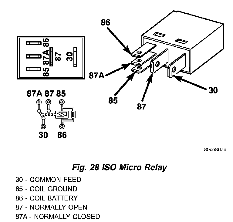
Fig.28 ISO Micro Relay:
WIPER ON/OFF RELAY
The wiper ON/OFF relay is located in the Power Distribution Center (PDC) in the engine compartment near the battery. The wiper ON/OFF relay is a conventional International Standards Organization (ISO) micro relay. Relays conforming to the ISO specifications have common physical dimensions, current capacities, terminal patterns, and terminal functions. The relay is contained within a small, rectangular, molded plastic housing and is connected to all of the required inputs and outputs by five integral male spade-type terminals that extend from the bottom of the relay base.
The wiper ON/OFF relay cannot be adjusted or repaired and, if faulty or damaged, the unit must be replaced.
The wiper ON/OFF relay is an electromechanical switch that uses a low current input from the Body Control Module (BCM) to control a high current output to the front wiper motor. The movable common feed contact point is held against the fixed normally closed contact point by spring pressure. When the relay coil is energized, an electromagnetic field is produced by the coil windings. This electromagnetic field draws the movable relay contact point away from the fixed normally closed contact point, and holds it against the fixed normally open contact point. When the relay coil is de-energized, spring pressure returns the movable contact point back against the fixed normally closed contact point. A resistor is connected in parallel with the relay coil in the relay, and helps to dissipate voltage spikes and electromagnetic interference that can be generated as the electromagnetic field of the relay coil collapses.
The wiper ON/OFF relay terminals are connected to the vehicle electrical system through a connector receptacle in the Power Distribution Center (PDC). The inputs and outputs of the wiper ON/OFF relay include:
- Common Feed Terminal - The common feed terminal (30) is connected to the common feed terminal of the wiper high/low relay at all times through the wiper ON/OFF relay output circuit.
- Coil Ground Terminal - The coil ground terminal (85) is connected to a control output of the Body Control Module (BCM) through a front wiper ON/OFF relay control circuit. The BCM controls front wiper motor operation by controlling a ground path through this circuit.
- Coil Battery Terminal - The coil battery terminal (86) receives battery current at all times from a circuit breaker in the Junction Block (JB) through a fused ignition switch output (run-acc) circuit.
- Normally Open Terminal - The normally open terminal (87) receives battery current at all times from a circuit breaker in the Junction Block (JB) through a fused ignition switch output (run-acc) circuit, and provides battery current to the front wiper ON/OFF relay output circuit whenever the relay is energized.
- Normally Closed Terminal - The normally closed terminal (87A) is connected to the wiper park switch in the front wiper motor through the front wiper park switch sense circuit, and is connected to the wiper park switch whenever the relay is de-energized.
The wiper ON/OFF relay can be diagnosed using conventional diagnostic tools and methods.