Part 4 of 5
Fig.14 Rain Sensor Module:
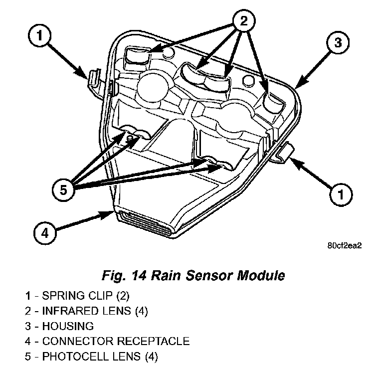
RAIN SENSOR MODULE
The Rain Sensor Module (RSM) is the primary component of the automatic wiper system. The RSM is located on the inside of the windshield, between the rear view mirror mounting button and the windshield header and is concealed behind a molded plastic trim cover that snaps over the module housing. The triangular-shaped molded black plastic housing of the RSM has a rectangular opening located on the upper end of the housing for the module connector receptacle, which contains four terminal pins. These terminal pins connect the rain sensor to the vehicle electrical system through a dedicated take out and connector of the overhead wire harness that extends from above the headliner. Five openings on the windshield side of the RSM housing are fitted with eight convex clear plastic lenses. A metal spring clip on each side of the housing near the bottom secures the RSM to a plastic mounting bracket that is bonded to the windshield glass. Concealed within the RSM housing is the electronic circuitry of the module, which includes four Infrared (IR) diodes, two photocells, and a microprocessor.
The RSM software is Flash compatible, which means it can be reprogrammed using Flash reprogramming procedures. However, if any of the hardware of the RSM is damaged or faulty, the entire module must be replaced. The RSM bracket is serviced as a unit with the windshield glass. If the bracket is faulty, damaged, or separated from the windshield glass, the windshield unit must be replaced.
The microprocessor-based Rain Sensor Module (RSM) senses moisture in the wipe pattern on the outside of the windshield glass and sends wipe commands to the Body Control Module (BCM). Four Infrared (IR) diodes within the RSM generate IR light beams that are aimed by four of the convex optical lenses near the base of the module through the windshield glass. Four additional convex optical lenses near the top of the RSM are focused on the IR light beams on the outside of the windshield glass and allow the two photocells within the module to sense changes in the intensity of these IR light beams. When sufficient moisture accumulates within the wipe pattern of the windshield glass, the RSM detects a change in the monitored IR light beam intensity.
The internal programming of the RSM then sends the appropriate electronic wipe command messages to the BCM over the Programmable Communications Interface (PCI) data bus. The BCM responds by activating or deactivating the front wiper system. The BCM also sends electronic sensitivity level messages to the RSM over the PCI data bus based upon the driver-selected sensitivity setting of the control knob on the control stalk of the right (wiper) multi-function switch. The higher the selected sensitivity setting the more sensitive the RSM is to the accumulated moisture on the windshield glass, and the more frequently the RSM will send wipe commands to the BCM to operate the front wiper system.
The RSM operates on battery current received through a fuse in the Junction Block (JB) on a fused B(+) circuit. This circuit is switched by the power accessory (sunroof) delay relay in the JB so that the RSM will operate whenever the relay is energized by the BCM. The RSM receives ground at all times through a take out of the left body wire harness with an eyelet terminal that is secured by a ground screw to the front seat crossmember on the floor panel under the left front seat. It is important to note that the default condition for the wiper system is automatic wipers Off; therefore, if no message is received from the RSM by the BCM for more than about five seconds, the automatic wipers will be disabled and the BCM will default the front wiper system operation to the low speed continuous wipe mode.
The RSM ground and battery current inputs can be diagnosed using conventional diagnostic tools and methods. However, conventional diagnostic methods may not prove conclusive in the diagnosis of the RSM internal circuitry, the BCM, the PCI data bus network, or the electronic messages received and transmitted by the RSM over the PCI data bus. The most reliable, efficient, and accurate means to diagnose the RSM requires the use of a DRB III scan tool. Refer to the appropriate diagnostic information.
Fig.16 Right (Wiper) Multi-Function Switch:
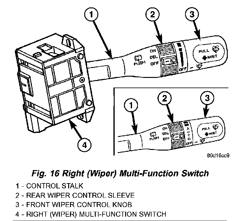
RIGHT MULTI-FUNCTION SWITCH
The right (wiper) multi-function switch is secured to the right side of the multi-function switch mounting housing at the top of the steering column, just below the steering wheel. The only visible component of the right multi-function switch is the control stalk that extends through a dedicated opening in the right side of the steering column shrouds. The remainder of the right multi-function switch is concealed beneath the steering column shrouds. The switch housing and its control stalk are constructed of molded black plastic. A single connector receptacle containing up to ten terminal pins is located on the back of the switch housing and connects the switch to the vehicle electrical system through a take out and connector of the instrument panel wire harness. The switch is secured to the multi-function switch mounting housing near the top of the steering column by two screws.
There are two versions of the right multi-function switch: one to support the standard equipment speed sensitive intermittent front wiper system, and a second to support the optional front automatic wiper system. Each version of the right multi-function switch control stalk has both white nomenclature and International Control and Display Symbol icons applied to it, which clearly identify its many functions. The control stalk has a control knob on its end with a flattened face to allow it to be easily rotated. Just below the control knob is a knurled control sleeve. The right multi-function switch is the primary control for the front and rear wiper and washer systems, and contains switches and circuitry to provide signals to the Body Control Module (BCM) and the rear wiper module.
The right (wiper) multi-function switch cannot be adjusted or repaired. If any function of the switch is faulty or if the switch is damaged, the entire switch unit must be replaced.
The right (wiper) multi-function switch supports the following functions and features:
- Automatic Front Wipe Mode - On models equipped with the optional automatic wiper system, the internal circuitry and hardware of the right (wiper) multi-function switch control knob provide an automatic front wipe mode with five sensitivity positions.
- Continuous Front Wipe Modes - The internal circuitry and hardware of the right (wiper) multifunction switch control knob provide two continuous front wipe switch positions, low speed or high speed.
- Continuous Rear Wipe Mode - The internal circuitry and hardware of the right (wiper) multi-function switch control sleeve provides one continuous rear wipe switch position.
- Front Washer Mode - The internal circuitry and hardware of the right (wiper) multi-function switch control stalk provide front washer system operation.
- Front Wipe-After-Wash Mode - The internal circuitry and hardware of the right (wiper) multi- function switch control stalk provide a wipe-after- wash mode.
- Front Wiper Mist Mode - The internal circuitry and hardware of the right (wiper) multi-function switch control stalk provide a front wiper system mist mode.
- Intermittent Front Wipe Mode - The internal circuitry and hardware of the right (wiper) multi- function switch control knob provide an intermittent front wipe mode with five delay interval positions, except on models equipped with the optional automatic wiper system.
- Intermittent Rear Wipe Mode - The internal circuitry and hardware of the right (wiper) multi- function switch control ring provide one fixed interval intermittent rear wipe mode switch position.
- Rear Washer Mode - The internal circuitry and hardware of the right (wiper) multi-function switch control stalk provide rear washer system operation.
The right (wiper) multi-function switch uses a combination of resistor multiplexed and conventionally switched outputs to control the many functions and features it provides. The switch receives battery current on a fused ignition switch output (run-acc) circuit from a fuse in the Junction Block (JB) whenever the ignition switch is in the ON or Accessory positions, and receives ground from the Body Control Module (BCM) on a windshield wiper switch return circuit. The right (wiper) multi-function switch may be diagnosed using conventional diagnostic tools and methods.
Following are descriptions of how the right (wiper) multi-function switch control stalk operates to control the functions and features it provides:
- Automatic Wipe Mode - On models equipped with the optional automatic wiper system, the control knob on the end of the right (wiper) multi-function switch control stalk is rotated to one of five minor intermediate detents to select the desired automatic wipe sensitivity level. The control knob is rotated rearward (counterclockwise) to reduce the sensitivity (increase the interval between wipes), or forward (clockwise) to increase the sensitivity (decrease the interval between wipes). The right (wiper) multi-function switch provides a resistor multiplexed output to the Body Control Module (BCM) on a windshield wiper switch mux circuit. The BCM responds by sending an electronic message to the Rain Sensor Module (RSM) over the Programmable Communications Interface (PCI) data bus indicating the selected sensitivity level, and by operating the front wiper system based upon electronic wipe commands received from the RSM over the PCI data bus.
- Continuous Front Wipe Modes - The control knob on the end of the right (wiper) multi-function switch control stalk is rotated to an intermediate detent that is one detent rearward (counterclockwise) from the full forward (clockwise) detent to select the low speed continuous front wiper mode, or to its full forward (clockwise) detent to select the high speed continuous front wiper mode. For the low speed mode, the multi-function switch provides a resistor multiplexed output to the Body Control Module (BCM) on a windshield wiper switch mux circuit, and the BCM responds by energizing the wiper on/off relay in the Power Distribution Center (PDC) for the front low speed continuous wipe mode. For the high speed mode, the multi-function switch provides the same resistor multiplexed output to the BCM on the windshield wiper switch mux circuit as the low speed mode, but also provides a ground output to the BCM on a wiper high control circuit. The BCM responds to these inputs by energizing the wiper on/off relay and the wiper high/low relay in the PDC for the front high speed continuous wipe mode.
- Continuous Rear Wipe Mode - The control ring on the right (wiper) multi-function switch control stalk is rotated to the most forward (clockwise) detent to select the continuous rear wiper mode. The multi-function switch provides a battery current output to the rear wiper motor on a rear wiper motor control circuit to signal the rear wiper module to operate the rear wiper motor in the continuous wipe mode.
- Front Washer Mode - The control stalk of the right (wiper) multi-function switch is pulled toward the steering wheel to momentarily activate the front washer pump/motor in the front washer mode. The front washer pump will continue to operate in the front washer mode until the control stalk is released. The right (wiper) multi-function switch provides a battery current output on a washer pump motor switch output circuit to energize the front washer pump in the front washer mode.
- Front Wiper Mist Mode - The control stalk of the right (wiper) multi-function switch is pushed towards the floor to momentarily activate the front wiper motor in the mist mode. The front wiper motor will continue to operate in the mist mode until the control stalk is released. The right (wiper) multi-function switch provides a resistor multiplexed output to the Body Control Module (BCM) on a windshield wiper switch mux circuit, and the BCM responds by energizing the wiper on/off relay in the Power Distribution Center (PDC) to operate the front wiper motor momentarily at low speed to provide the front wiper mist mode.
- Intermittent Front Wipe Mode - On models not equipped with the optional automatic wiper system, the control knob on the end of the right (wiper) multi-function switch control stalk is rotated to one of five minor intermediate detents to select the desired intermittent front wipe delay interval. The control knob is rotated rearward (counterclockwise) to increase the delay, or forward (clockwise) to decrease the delay The right (wiper) multi-function switch provides a resistor multiplexed output to the Body Control Module (BCM) on a windshield wiper switch mux circuit. The BCM responds by monitoring electronic vehicle speed messages received from the Powertrain Control Module (PCM) over the Programmable Communications Interface (PCI) data bus, then energizing the wiper on/off relay in the Power Distribution Center (PDC) to operate the front wiper motor at the proper delay intervals.
- Intermittent Rear Wipe Mode - The control ring on the right (wiper) multi-function switch control stalk is rotated to the center detent to select the intermittent rear wiper mode. The right (wiper) multi-function switch provides a battery current output to the rear wiper motor on a rear wiper motor delay control circuit to signal the rear wiper module to operate the rear wiper in the intermittent wipe mode.
- Rear Washer Mode - The right (wiper) multi- function switch control stalk is pushed forward toward the instrument panel to a momentary positions to activate the rear washer pump/motor in the rear washer mode. The rear washer pump will continue to operate in the rear washer mode until the control stalk is released. The right (wiper) multi-function switch provides battery current on a rear washer pump motor control circuit to energize the rear washer pump in the rear washer mode.