Part 1 of 5
Fig.1 Front Wiper & Washer System:
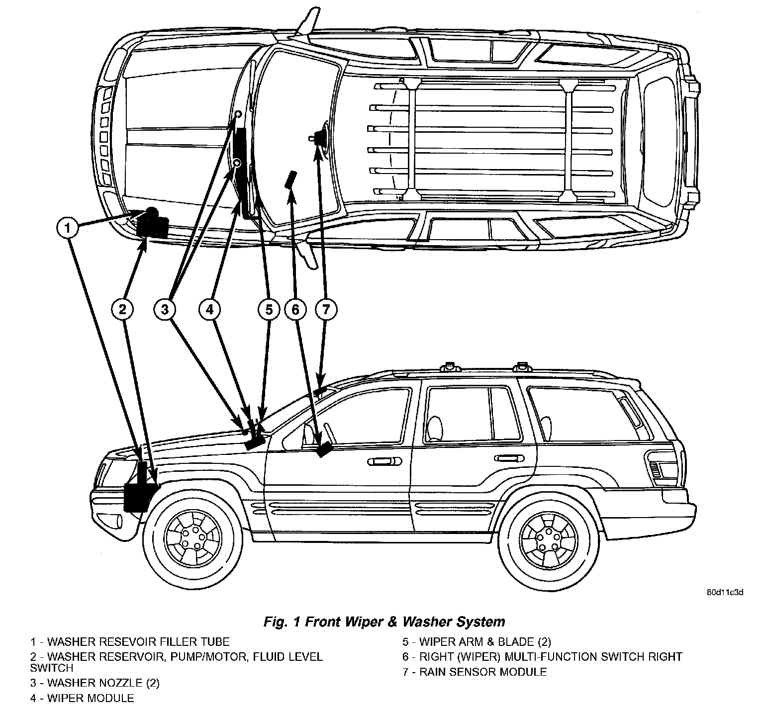
FRONT WIPERS/WASHERS
An electrically operated intermittent front wiper and washer system is standard factory-installed safety equipment on this model. The front wiper and washer system includes the following major components, which are described in further detail elsewhere in this service information:
- Body Control Module - The Body Control Module (BCM) is located on the Junction Block (JB) under the driver side outboard end of the instrument panel. (Refer to ELECTRICAL/ELECTRONIC CONTROL MODULES/BODY CONTROL MODULE - DESCRIPTION).
- Front Check Valve - The front washer system check valve is integral to the wye fitting located in the washer plumbing between the cowl plenum washer hose and the front washer nozzles, and is concealed beneath the cowl plenum cover/grille panel at the base of the windshield.
- Front Washer Nozzle - Two fluidic front washer nozzles are secured with integral snap features to dedicated openings in the cowl plenum coven grille panel located near the base of the windshield.
- Front Washer Plumbing - The plumbing for the front washer system consists of rubber hoses and molded plastic fittings. The plumbing is routed along the left side of the engine compartment from the washer reservoir, and through the dash panel into the cowl plenum to the front washer nozzle fittings beneath the cowl plenum cover/grille panel.
- Front Washer Pump/Motor - The front washer pump/motor unit is located in a dedicated hole on the lower outboard side of the washer reservoir, behind the inner fender liner ahead of the left front wheel. The front washer pump is located ahead of and below the rear washer pump.
- Front Wiper Arm - The two front wiper arms are secured with nuts to the threaded studs on the ends of the two wiper pivot shafts, which extend through the cowl plenum cover/grille panel located near the base of the windshield.
- Front Wiper Blade - The two front wiper blades are secured to the two front wiper arms with an integral latch, and are parked on the glass near the bottom of the windshield when the front wiper system is not in operation.
- Front Wiper Module - The front wiper pivot shafts are the only visible components of the front wiper module. The remainder of the module is concealed within the cowl plenum beneath the cowl plenum cover/grille panel. The front wiper module includes the module bracket, four rubber-isolated wiper module mounts, the front wiper motor, the wiper motor crank arm, the two wiper drive links, and the two front wiper pivots.
- Rain Sensor Module - Models equipped with the optional automatic wiper feature have a Rain Sensor Module (RSM) located behind a trim cover on a bracket bonded to the inside surface of the windshield glass, just above the inside rear view mirror mounting button.
- Right Multi-Function Switch - The right (wiper) multi-function switch is secured to the right side of the multi-function switch mounting housing near the top of the steering column, just below the steering wheel. Only the control stalk for the right multi-function switch is visible, while the remainder of the switch is concealed beneath the steering column shrouds. The right multi-function switch contains all of the switches and control circuitry for both the front and rear wiper and washer systems.
- Washer Fluid Level Switch - The washer fluid level switch is located in a dedicated hole near the center of the forward surface of the washer reservoir, behind the left front wheel house splash shield.
- Washer Reservoir - The washer reservoir is concealed between the left inner fender shield and the left outer fender panel, behind the inner fender liner and ahead of the left front wheel. The washer reservoir filler neck is the only visible portion of the reservoir, and it is accessed from the left front corner of the engine compartment.
- Wiper High-Low Relay - The wiper high-low relay is an International Standards Organization (ISO) micro relay located in the Power Distribution Center (PDC) in the engine compartment near the battery.
- Wiper ON-OFF Relay - The wiper ON-OFF relay is an International Standards Organization (ISO) micro relay located in the Power Distribution Center (PDC) in the engine compartment near the battery.
Hard wired circuitry connects the front wiper and washer system components to the electrical system of the vehicle. These hard wired circuits are integral to several wire harnesses, which are routed throughout the vehicle and retained by many different methods. These circuits may be connected to each other, to the vehicle electrical system and to the front wiper and washer system components through the use of a combination of soldered splices, splice block connectors, and many different types of wire harness terminal connectors and insulators. Refer to the appropriate wiring information. The wiring information includes wiring diagrams, proper wire and connector repair procedures, further details on wire harness routing and retention, as well as pin-out and location views for the various wire harness connectors, splices and grounds.
The front wiper and washer system is designed to provide the vehicle operator with a convenient, safe, and reliable means of maintaining visibility through the windshield glass. The various components of this system are designed to convert electrical energy produced by the vehicle electrical system into the mechanical action of the wiper blades to wipe the outside surface of the glass, as well as into the hydraulic action of the washer system to apply washer fluid stored in an on-board reservoir to the area of the glass to be wiped. When combined, these components provide the means to effectively maintain clear visibility for the vehicle operator by removing excess accumulations of rain, snow, bugs, mud, or other minor debris that might be encountered while driving the vehicle under numerous types of inclement operating conditions from the outside windshield glass surface.
The vehicle operator initiates all front wiper and washer system functions with the control stalk of the right (wiper) multi-function switch that extends from the right side of the steering column, just below the steering wheel. Rotating the control knob on the end of the right (wiper) multi-function switch control stalk selects the OFF, Delay (on models not equipped with the optional automatic wiper system), Auto (on models equipped with the optional automatic wiper system), Low, or High front wiper system operating modes. In the Delay mode, the control knob also allows the vehicle operator to select from one of five intermittent wipe Delay intervals. In the Auto mode, the control knob also allows the vehicle operator to select from one of five automatic wiper sensitivity levels. Pulling the right control stalk downwards actuates the momentary front wiper system Mist mode switch, while pulling the right control stalk towards the steering wheel actuates the front washer system switch. The multi-function switch provides hard wired resistor multiplexed inputs to the Body Control Module (BCM) for all of the front wiper system functions, as well as separate hard wired sense inputs to the BCM for the high speed continuous wipe and front washer system functions.
The front wiper and washer system will only operate when the ignition switch is in the Accessory or ON positions. Battery current is directed from a B(+) fuse in the Power Distribution Center (PDC) to the wiper and washer system circuit breaker in the Junction Block (JB) through a fused ignition switch output (run-acc) circuit. The automatic resetting circuit breaker then provides battery current through a fused ignition switch output (run-acc) circuit to the wiper ON/OFF relay, and the park switch in the front wiper motor. A separate fuse in the JB provides battery current through another fused ignition switch output (run-acc) circuit to the right multi-function switch. The right multi-function switch circuitry uses this battery feed to directly control the operation of the front washer pump/motor unit. The BCM uses low side drivers to control front wiper system operation by energizing or de-energizing the wiper high/ low and wiper ON/OFF relays.
The hard wired circuits and components of the front wiper and washer system may be diagnosed and tested using conventional diagnostic tools and procedures. However, conventional diagnostic methods may not prove conclusive in the diagnosis of the Body Control Module (BCM), or the inputs to or outputs from the BCM that control the front wiper and washer system operating modes. The most reliable, efficient, and accurate means to diagnose the BCM, or the BCM inputs and outputs related to the various front wiper and washer system operating modes requires the use of a DRB III scan tool. Refer to the appropriate diagnostic information.
Following are paragraphs that briefly describe the operation of each of the front wiper and washer system operating modes.
Operating Modes
The components of the front wiper and washer system are designed to work in concert to provide the following operating modes:
- Automatic Wiper - In models equipped with the optional automatic wiper feature, the internal circuitry of both the right (wiper) multi-function switch, the rain sensor module, and the BCM work in concert to provide an automatic wiper mode with five sensitivity selections. The BCM tells the Rain Sensor Module (RSM) when the automatic wiper mode is selected and the manually selected sensitivity level, then the rain sensor module tells the BCM each time enough water droplets have accumulated within the wipe pattern on the windshield to require front wiper operation. The BCM then automatically operates the front wipers at the programmed speed and intervals requested by the RSM to maintain visibility through the windshield.
- Continuous Wipe Mode - The control knob on the control stalk of the right (wiper) multi-function switch has two continuous wipe positions, Low and High. When selected, these switch positions will cause the two-speed front wiper motor to operate in a continuous low or high speed cycle.
- Headlamps ONWith Wipers - The BCM provides an automatic headlamps on with wipers feature for models equipped with the optional automatic headlamps. This is a customer programmable feature. If this feature is enabled, the headlamps will turn ON automatically when the windshield wipers are turned on; and, if the headlamps were turned ON automatically when the wipers were turned on, they will turn OFF automatically when the wipers are turned OFF. In models equipped with the optional automatic wiper feature, when the automatic wiper mode is selected the headlamps will turn ON automatically only after the wipers complete three automatic wipe cycles within about 30 seconds, and they will turn OFF automatically after 3 minutes elapse without any automatic wipe cycles. (Refer to ELECTRICAL/OVERHEAD CONSOLE - STANDARD PROCEDURE - ELECTRONIC VEHICLE INFORMATION CENTER PROGRAMMING).
- Mist Wipe Mode - The control stalk of the right (wiper) multi-function switch has a momentary Mist position. When selected, this switch position will operate the front wipers in a low speed continuous cycle for as long as the switch is held closed, then will complete the current wipe cycle and park the front wiper blades near the base of the windshield when the switch is released.
- Speed Sensitive Intermittent Wipe Mode - Except on models equipped with the optional automatic wiper system, the internal circuitry of both the right (wiper) multi-function switch and the BCM work in concert to provide an intermittent wipe mode with five delay interval selections. The BCM automatically adjusts each manually selected delay interval to compensate for vehicle speed.
- Washer Mode - When the momentary front wash position of the control stalk for the right (wiper) multi-function switch is selected with the front wiper system operating in a continuous wipe mode, washer fluid will be dispensed onto the windshield glass through the washer nozzles for as long as the washer switch is held closed. When the front washer switch is actuated with the front wiper system operating in an intermittent wipe mode, washer fluid is still dispensed until the switch is released; however, the front wipers will operate in a low speed continuous cycle from the time the washer switch is closed until several wipe cycles after the switch is released, before returning to the selected intermittent wipe mode.
- Wipe-After-Wash Mode - When the momentary front wash position of the control stalk for the right (wiper) multi-function switch is selected with the front wiper system turned OFF, the internal circuitry of the BCM provides a wipe-after-wash feature. When selected, this feature will operate the front washer pump/motor and the front wipers for as long as the front washer switch is held closed, then provide several additional wipe cycles after the switch is released before parking the front wiper blades near the base of the windshield.
Continuous Wipe Mode
When the Low position of the control knob on the control stalk of the right (wiper) multi-function switch is selected, the Body Control Module (BCM) energizes the wiper ON/OFF relay. This directs battery current through the normally open contacts of the energized wiper ON/OFF relay and the normally closed contacts of the de-energized wiper high/low relay to the low speed brush of the front wiper motor, causing the front wipers to cycle at low speed. When the High position of the control knob is selected, the BCM energizes both the wiper ON/OFF relay and the wiper high/low relay This directs battery current through the normally open contacts of the energized wiper ON/OFF relay and the normally open contacts of the energized wiper high/low relay to the high speed brush of the front wiper motor, causing the front wipers to cycle at high speed.
When the OFF position of the control knob is selected, the BCM de-energizes both the wiper ON/OFF and wiper high/low relays, then one of two events will occur. The event that will occur depends upon the position of the wiper blades on the windshield at the moment that the control knob OFF position is selected. If the wiper blades are in the down position on the windshield when the OFF position is selected, the park switch that is integral to the front wiper motor is closed to ground and the wiper motor ceases to operate. If the wiper blades are not in the down position on the windshield at the moment the OFF position is selected, the park switch is closed to battery current from the fused ignition switch output (run-acc) circuit of the front wiper motor. The park switch directs this battery current to the low speed brush of the wiper motor through the wiper park switch sense circuit and the normally closed contacts of the wiper ON/OFF and wiper high/low relays. This causes the wiper motor to continue running at low speed until the wiper blades are in the down position on the windshield and the park switch is again closed to ground.
Intermittent Wipe Mode
On models not equipped with the optional automatic wiper system, when the control knob on the control stalk of the right (wiper) multi-function switch is moved to one of the five Delay interval positions, the BCM electronic intermittent wipe logic circuit responds by calculating the correct length of time between wiper sweeps based upon the selected delay interval input. The BCM monitors the changing state of the wiper motor park switch through a hard wired front wiper park switch sense circuit input. This input allows the BCM to determine the proper intervals at which to energize and de-energize the wiper ON/OFF relay to operate the front wiper motor intermittently for one low speed cycle at a time. The BCM logic is also programmed to provide an immediate wipe cycle and begin a new delay interval timing cycle each time a shorter delay interval is selected, and to add the remaining delay timing interval to the new delay interval timing before the next wipe cycle occurs each time a longer delay interval is selected.
The intermittent wipe mode delay times are speed sensitive. The BCM monitors vehicle speed messages received from the Powertrain Control Module (PCM) over the Programmable Communications Interface (PCI) data bus network in order to provide the speed sensitive delay intervals. Above about 16 km/h (10 mph) the delay is driver adjustable from about 1/2 second to about 18 seconds. Below about 16 km/h (10 mph) the delay times are doubled, from about 1 second to about 36 seconds.
Automatic Wipe Mode
On models equipped with the optional automatic wiper system, when the control knob on the control stalk of the right (wiper) multi-function switch is moved to one of the five Auto sensitivity positions, the BCM sends an electronic message to the Rain Sensor Module (RSM) over the Programmable Communications Interface (PCI) data bus network indicating the selected position. The RSM monitors an area within the wipe pattern of the windshield glass for the accumulation of moisture. Based upon internal programming and the selected sensitivity level, when sufficient moisture has accumulated the RSM sends the appropriate electronic wipe command messages to the BCM over the PCI data bus and the BCM operates the front wiper system accordingly. As the sensitivity level is set higher, the RSM is more sensitive to moisture accumulation and will send wipe commands more frequently. The BCM logic is also programmed to provide an immediate wipe cycle each time the control knob on the control stalk of the right multi-function switch is moved from a non-automatic wipe position to one of the five Auto sensitivity positions, and another immediate wipe cycle each time the control knob is moved from a lower Auto sensitivity position to a higher Auto sensitivity position.
Mist Wipe Mode
When the control stalk of the right (wiper) multi-function switch is moved to the momentary Mist position, the BCM energizes the wiper ON/OFF relay for as long as the Mist switch is held closed, then de-energizes the relay when the state of the Mist switch input changes to open. The BCM can operate the front wiper motor in this mode for only one low speed cycle at a time, or for an indefinite number of sequential low speed cycles, depending upon how long the Mist switch is held closed.
Wash Mode
When the control stalk of the right (wiper) multi-function switch is moved to the momentary front Wash position while the control knob is in the Low or High positions, the circuitry within the switch directs battery current to the front washer pump/motor unit. This will cause the front washer pump/motor unit to be energized for as long as the front Wash switch is held closed, and to de-energize when the front Wash switch is released. When the control stalk of the right (wiper) multi-function switch is moved to the momentary front Wash position while the control knob is in one of the Delay interval or Auto sensitivity positions, the front washer pump/motor operation is the same. However, the BCM energizes the wiper ON/OFF relay to override the selected delay interval or auto sensitivity level and operate the front wiper motor in a continuous low speed mode for as long as the front Wash switch is held closed, then de-energizes the relay and reverts to the selected delay mode interval or auto sensitivity level several wipe cycles after the front Wash switch is released. The BCM detects the front Wash switch state through a hard wired washer pump motor switch output circuit input from the right multi-function switch.
Wipe-After-Wash Mode
When the control stalk of the right (wiper) multi-function switch is moved to the momentary front Wash position while the control knob is in the OFF position, the BCM detects that switch state through a hard wired washer pump motor switch output circuit input from the right multi-function switch. The BCM responds to this input by energizing the wiper ON/OFF relay for as long as the Wash switch is held closed, then de-energizes the relay several wipe cycles after the front Wash switch is released. The BCM monitors the changing state of the wiper motor park switch through a hard wired front wiper park switch sense circuit input. This input allows the BCM to count the number of wipe cycles that occur after the front Wash switch state changes to open, and to determine the proper interval at which to deenergize the wiper ON/OFF relay to complete the wipe-after-wash mode cycle.