Standard Procedure - Propeller Shaft Angle
STANDARD PROCEDURESThis procedure applies to both the front propeller shafts and the rear propeller shaft. To obtain the front (output) angle on the C/V front propeller shaft, the inclinometer is placed on the machined ring of the pinion flange. To obtain the propeller shaft angle measurement on the C/V front propeller shaft, the inclinometer is placed on the propeller shaft tube.
PROPELLER SHAFT ANGLE
1. Raise and support the vehicle at the axles as level as possible. Allow the wheels and propeller shaft to turn.
2. Remove any external bearing snap rings from universal joint if equipped, so the inclinometer base will sits flat.
3. Rotate the shaft until transmission/transfer case output yoke bearing cap is facing downward, if necessary.
NOTE: Always make measurements from front to rear.
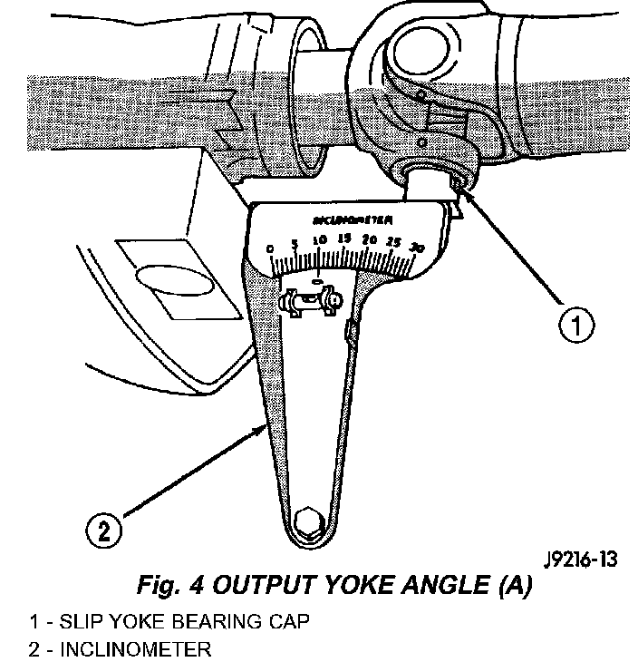
4. Place Inclinometer on yoke bearing cap, or the pinion flange ring, (A) parallel to the shaft (Fig. 4). Center bubble in sight glass and record measurement.
NOTE: This measurement will give you the transmission or Output Yoke Angle (A).
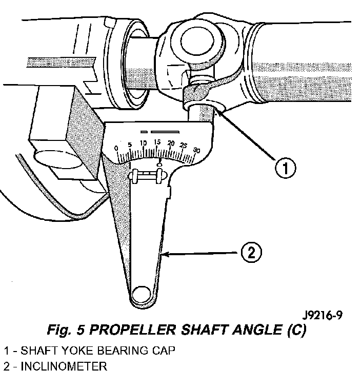
5. Rotate propeller shaft 90 degrees and place Inclinometer on yoke bearing cap, or propeller shaft tube on CN propeller shaft, parallel to the shaft (Fig. 5). Center bubble in sight glass and record measurement. This measurement can also be taken at the rear end of the shaft.
NOTE: This measurement will give you the propeller shaft angle (C).
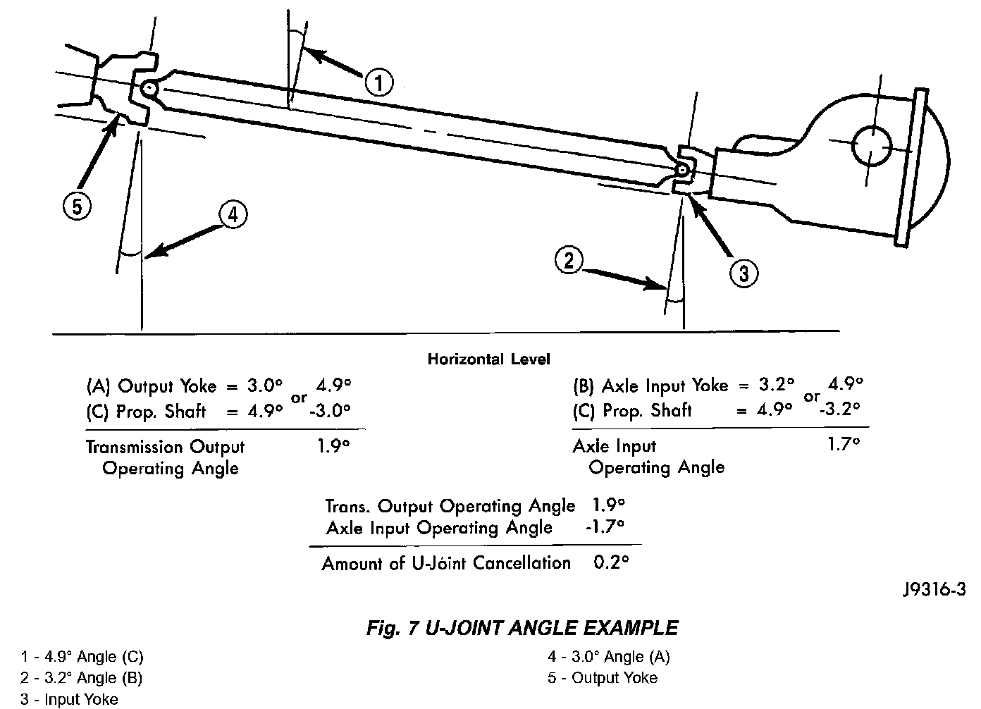
6. Subtract smaller figure from larger (C minus A) to obtain transmission output operating angle.
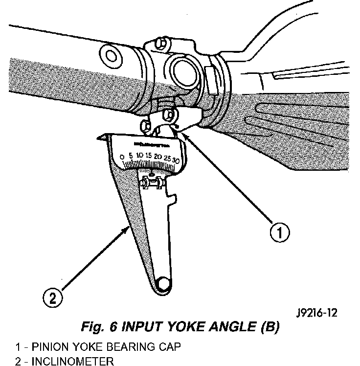
7. Rotate propeller shaft 90 degrees and place Inclinometer on pinion yoke bearing cap parallel to the shaft (Fig. 6). Center bubble in sight glass and record measurement.
NOTE: This measurement will give you the pinion shaft or input yoke angle (B).
8. Subtract smaller figure from larger (C minus B) to obtain axle Input Operating Angle.
Refer to rules given below and the example in (Fig. 7) for additional information.
- Good cancellation of U-joint operating angles (within 1 ').
- Operating angles less than 3°.
- Operating angles less than 10' for double cardan
U-joint.
- At least 1/2 of one degree continuous operating (propeller shaft) angle.
Propeller Shaft