Service Procedure
1. With the ignition key in the OFF position, disconnect the negative battery cable.Note:
To enhance customer satisfaction, remember to reset the clock when you have completed the service procedure.
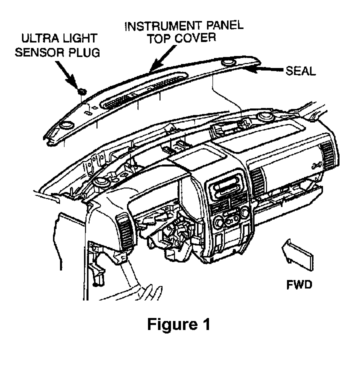
2. Using a trim stick or another suitable wide flat-bladed tool, gently pry the rear edge (farthest from the windshield) of the top cover up and away from the instrument panel (I/P) far enough to disengage the four (4) snap clip retainers (Figure 1).
3. Remove the top cover and set it aside.
4. Remove the left and right A-Pillar trim panels.
5. Remove the front bin from the center floor console.
6. Remove the ash tray bezel. Disconnect the auxiliary power outlet, lighter and heated seat switch electrical connectors and set the bezel aside.
7. Remove the radio bezel.
8. Remove the radio.
9. Remove the HVAC control unit.
10. Remove the I/P cluster bezel.
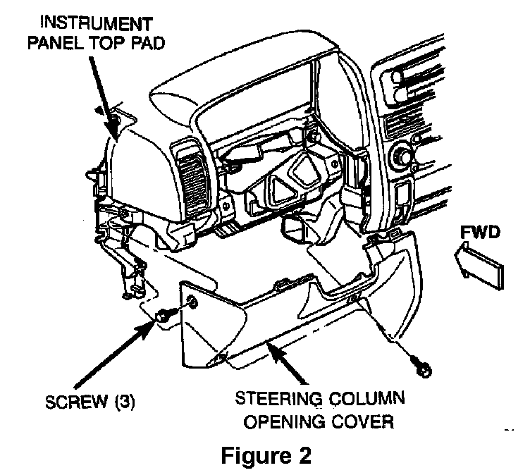
11. Remove five (5) screws from the steering column opening cover and then remove the cover (Figure 2).
12. Remove the I/P cluster.
13. Remove the left side I/P top pad screws (2) that were behind the steering column opening cover.
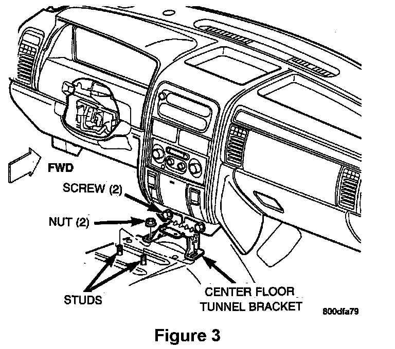
14. Remove the two (2) screws that secure the I/P to the center floor tunnel bracket (Figure 3).
15. Remove the two (2) nuts that secure the center floor tunnel bracket to the transmission tunnel. Set the support bracket aside (Figure 3).
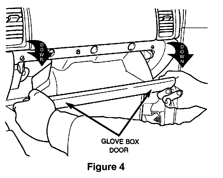
16. Open the glove box until the integral stops on the back edge of the glove box rest against the stop bumpers in the upper glove box opening reinforcement (Figure 4).
17. Reach into the glove box and with the middle finger of each hand, deflect the rubber flap of the two stop bumpers toward the front of the vehicle (Figure 4).
18. Roll the glove box door downward past the stops and then remove the glove box door.
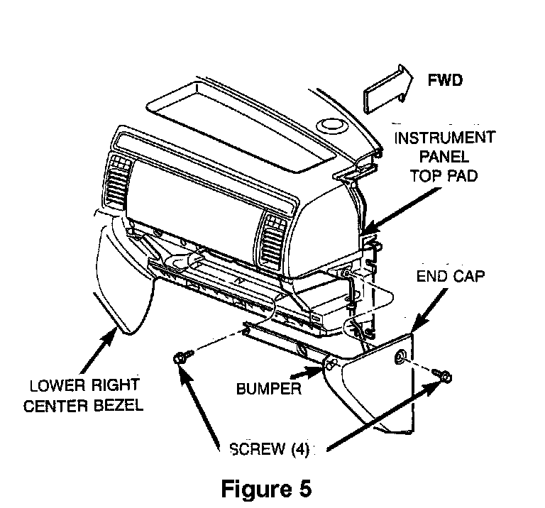
19. Remove the screws that secure the right I/P end cap to the I/P top pad and glove box opening. Disengage the snap clip and then remove the end cap (Figure 5).
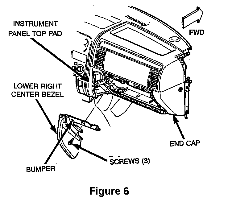
20. Remove the screws that secure the lower right center bezel to the I/P glove box opening. Disengage the two (2) snap clips and then remove the lower right center bezel (Figure 6).
21. Remove the right side I/P top pad screws (3) and bolts (2) from the glove box opening area.
22. Remove the screw above the radio location that secures the center of the I/P top pad.
23. Disconnect the speaker electrical connectors and harness clips on the top of the I/P.
24. Remove the Ultra Light sensor (if equipped) (Figure 1).
25. Remove the upper I/P top pad nuts (4) and screws (5) from along the top front edge of the top pad and then disconnect the defroster duct clips from the I/P top pad.
26. Remove the I/P top pad.
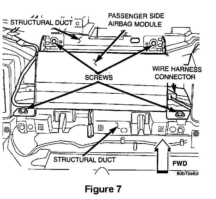
27. Disconnect the passenger airbag wiring harness connector (Figure 7).
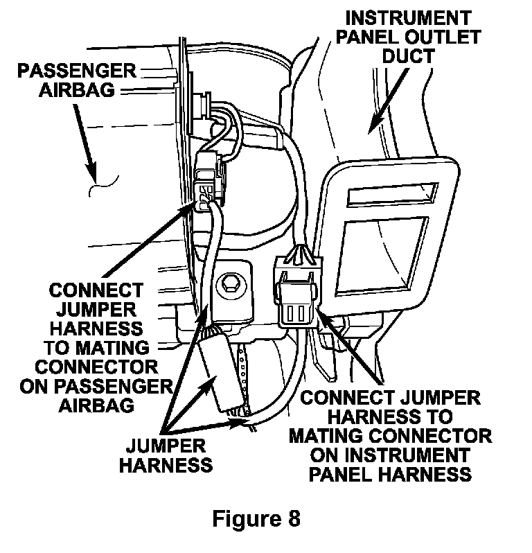
28. Connect one end of the supplied jumper harness to the connector attached to the side of the passenger airbag (Figure 8).
29. Connect the other end of the jumper harness to the mating connector on instrument panel wiring harness (Figure 8).
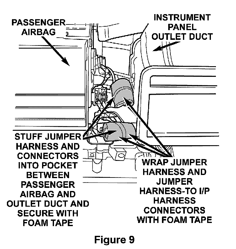
30. Wrap the connector in the center of jumper harness with foam tape (Figure 9).
NOTE:
Do NOT cover label that is attached to the jumper harness.
31. Wrap the jumper harness-to-instrument panel wiring harness connector with foam tape (Figure 9).
32. Stuff the jumper harness and connectors into the pocket between the passenger airbag and the instillment panel outlet duct. Secure the connectors to the instrument panel structural duct with foam tape (Figure 9).
NOTE:
To prevent customer I/P rattle complaints, jumper harness connectors must be wrapped with foam tape and secured to the structural duct.
33. Install the I/P top pad.
34. Connect the defroster duct clips to the I/P top pad and install the I/P top pad screws (5) and nuts (4).
35. Install the I/P ultra light sensor (if equipped) (Figure 1).
36. Connect the I/P speaker electrical connectors and harness clips.
37. Install the screw above the radio location that secures the center of the I/P top pad.
38. Install the right side I/P top pad screws (3) and bolts (2).
39. Install the right I/P end cap to the top pad and glove box opening (Figure 5). Tighten the screws securely.
40. Install the lower right center bezel (Figure 6). Tighten the screws that secure it to the I/P glove box opening securely.
41. Install the glove box door.
42. Install the center floor tunnel bracket and then install the two (2) screws that secure the I/P to the bracket (Figure 3).
43. Install the two (2) nuts that secure the center floor tunnel bracket to the transmission tunnel (Figure 3).
44. Install the left side I/P top pad screws (2).
45. Install the I/P cluster.
46. Install the steering column opening cover (Figure 2).
47. In stall the I/P cluster bezel.
48. Install the HVAC control unit.
49. Install the radio.
50. Install the radio bezel.
51. Connect the heated seat switch, lighter and auxiliary power outlet electrical connectors and then install the ash tray bezel.
52. Install the front bin into the center floor console.
53. Install the left and right A-Pillar trim panels.
54. Install the I/P top cover (Figure 1). Make sure that the four (4) snap clip retainers are engaged.
55. With the ignition switch in the ON position, connect the negative battery cable.
56. From outside the vehicle, turn the ignition switch to the OFF position for about 10 seconds and then back to the ON position.
57. Observe the airbag warning light in the instrument cluster. It should illuminate for 6-8 seconds and then go out.
NOTE:
If the airbag warning light fails to light or lights and stays on, there is a system malfunction. Refer to the proper Body Diagnostic Procedures manual to diagnose and repair the problem.