Fuel Tank - Premature Fueling Nozzle Shut Off
NUMBER: 14-006-01GROUP: Fuel
DATE: Oct. 12, 2001
SUBJECT:
Premature Fuel Nozzle Shut-Off When Filling Vehicle Fuel Tank
OVERVIEW:
This bulletin involves inspection of the evaporative canister vent hose for correct routing, and if necessary, the replacement of the evaporative canister assembly.
MODELS:
2002 (WJ) Grand Cherokee
SYMPTOM/CONDITION:
The customer may be concerned with filling their vehicle with fuel. The specific customer concern is repeated and premature fuel pump nozzle shut-off while filling the vehicle fuel tank.
DIAGNOSIS:
1. Raise and support the vehicle.
2. Remove the left rear tire and wheel assembly.
3. Drill out the five (5) rivets used to secure the left rear wheelhouse stone shield to the vehicle fascia and body.
4. Remove the stone shield.
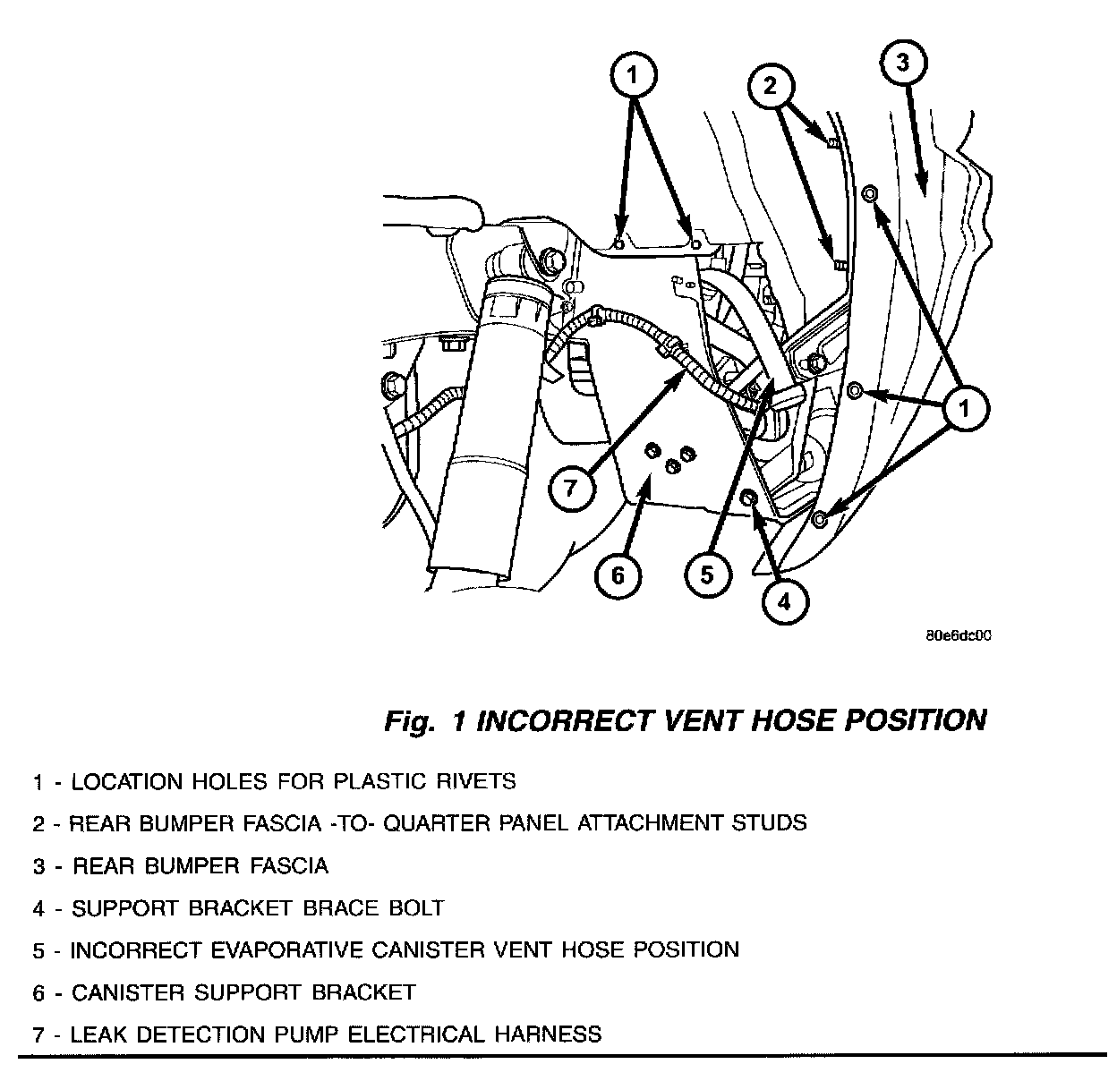
5. Refer to the illustration (Fig. 1). The evaporative canister vent hose should not be bent down as it may create a possible restriction in the venting of the evaporative system.
6. If the fuel nozzle shuts-off prematurely while filling the vehicle fuel tank, and the evaporative canister vent hose is bent down (as shown in the illustration), perform the Repair Procedure.

PARTS REQUIRED

EQUIPMENT REQUIRED
REPAIR PROCEDURE:
NOTE:
REFER TO THE 2002 GRAND CHEROKEE SERVICE MANUAL (P/N 81-370-02064) - EVAPORATIVE EMISSIONS, STARTING ON PAGE 25-24, FOR ADDITIONAL TECHNICAL ASSISTANCE. THE SERVICE MANUAL MAY ALSO BE FOUND ON MDS2.
1. If not performed previously, raise and support the vehicle, and remove the left rear wheel and tire assembly.
2. If not performed previously, remove the five (5) plastic rivets used to secure the left rear stone shield to the vehicle body.
3. At the left quarter panel area, remove the support bracket brace bolt from the evaporative canister support bracket.
4. Loosen, but do not remove, the two evaporative canister support bracket nuts.
5. Remove the upper rear canister support bracket bolt.
6. Carefully lower the canister support bracket and assembly to gain access to the vapor, vacuum, and electrical connections.
7. Disconnect the leak detection pump electrical connector, the vacuum line at the plastic tee, and the two vapor lines to the evaporative canister.
8. Remove the entire evaporative canister support bracket and assembly from the vehicle frame rail and discard.
9. Lower the vehicle.
10. While one end of the evaporative purge line has been removed from the canister, disconnect the other end of the evaporative purge line at the duty cycle purge valve (DCP). The DCP is located in the engine compartment near the brake booster. At the DCP end of the evaporative purge line, blow compressed air through the evaporative purge line to remove any contaminate or moisture that may be present in the line. Clean both ports on DCP valve. Reassemble the evaporative purge line to the DCP valve.
11. Raise the vehicle.
12. Loosely install the new evaporative canister support bracket and assembly, p/n 53013630AF, to the front two support bracket nuts.
13. Carefully install the two vapor lines to the evaporative canister. Connect the vacuum line to the plastic vacuum tee. Connect and lock the electrical connector to the leak detection pump.
NOTE:
VERIFY THAT ALL CONNECTIONS ARE CORRECT AND FIRMLY CONNECTED BEFORE PROCEEDING FURTHER.
14. Raise the canister support bracket to the frame rail. Install the upper rear support bracket bolt. Finish installing the two front support bracket nuts. Tighten the support bracket nuts and bolt to 28 Nm (250 in. lbs.).
15. Install the support bracket brace bolt.
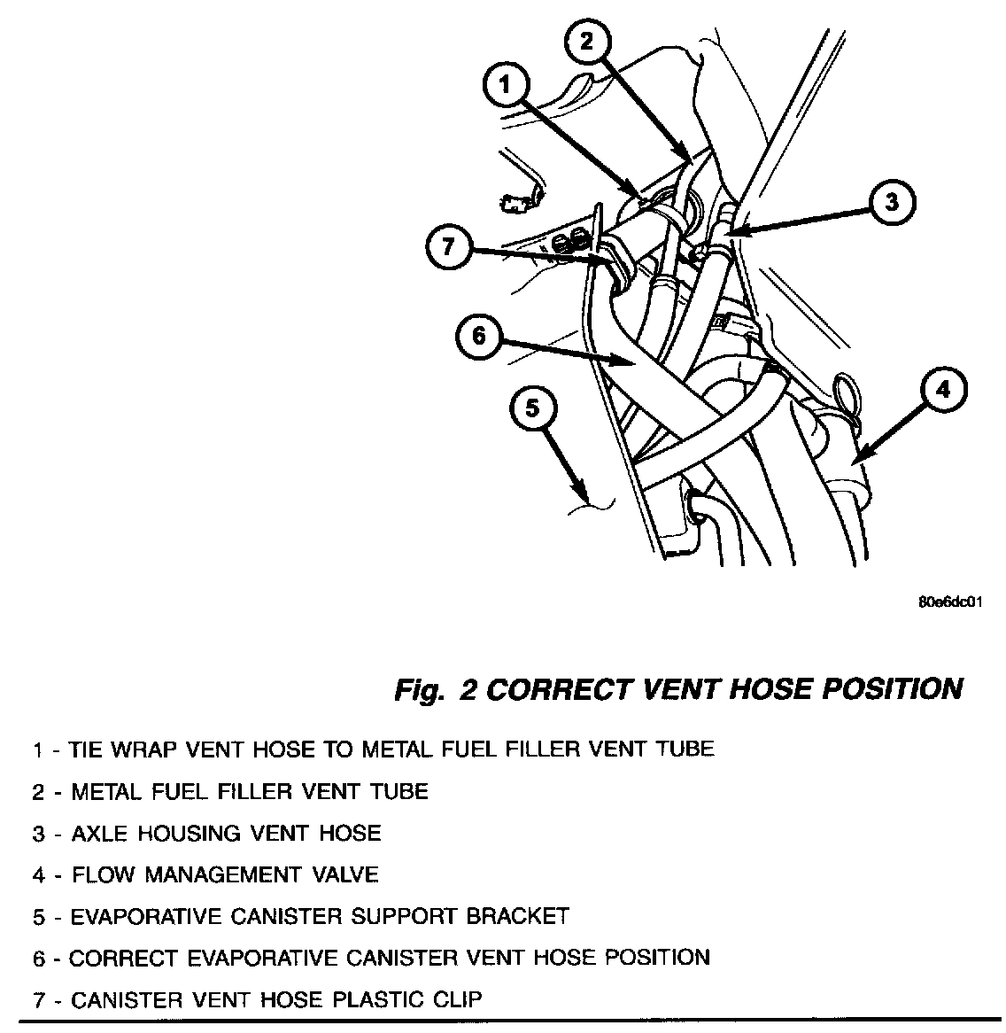
16. Verity that the evaporative canister vent hose is routed through the plastic clip and is positioned next to the fuel filler metal vent tube. Tie wrap the evaporative canister vent hose to the fuel filler metal vent tube. The vent hose must be pointing up. (Fig. 2).
NOTE:
THE VENT HOSE MUST BE SECURELY TIE WRAPPED TO THE FUEL FILLER METAL VENT TUBE, BUT DO NOT CRUSH VENT HOSE.
17. Lower the vehicle.
18. Using the DRB III(R), perform an evaporative system leak test to verity that no leaks are present in the evaporative system.
19. Raise the vehicle.
20. Install the left rear stone shield and new rivets, p/n 34201631.
21. Install the left rear wheel and tire assembly to the rear axle. Tighten the wheel lug nuts to 136 Nm (100 ft. lbs.).
22. Lower the vehicle.
POLICY:
Reimbursable within the provisions of the warranty.

TIME ALLOWANCE

FAILURE CODE