Instrument Cluster Disassembly and Assembly
DISASSEMBLY
Some of the components for the instrument cluster used in this vehicle are serviced individually. The serviced components include: the incandescent instrument cluster indicator and illumination lamp bulbs (including the integral bulb holders), the cluster lens, hood and mask unit, and the cluster housing rear cover. Following are the procedures for disassembling these components from the instrument cluster unit.
WARNING:
- ON VEHICLES EQUIPPED WITH AIRBAGS, DISABLE THE SUPPLEMENTAL RESTRAINT SYSTEM BEFORE ATTEMPTING ANY STEERING WHEEL, STEERING COLUMN, DRIVER AIRBAG, PASSENGER AIRBAG, SIDE CURTAIN AIRBAG, FRONT IMPACT SENSOR, SIDE IMPACT SENSOR, OR INSTRUMENT PANEL COMPONENT DIAGNOSIS OR SERVICE. DISCONNECT AND ISOLATE THE BATTERY NEGATIVE (GROUND) CABLE, THEN WAIT TWO MINUTES FOR THE SYSTEM CAPACITOR TO DISCHARGE BEFORE PERFORMING FURTHER DIAGNOSIS OR SERVICE. THIS IS THE ONLY SURE WAY TO DISABLE THE SUPPLEMENTAL RESTRAINT SYSTEM. FAILURE TO TAKE THE PROPER PRECAUTIONS COULD RESULT IN ACCIDENTAL AIRBAG DEPLOYMENT AND POSSIBLE PERSONAL INJURY.
- ON VEHICLES EQUIPPED WITH THE PREMIUM INSTRUMENT CLUSTER, THE CLUSTER CIRCUITRY PROVIDES AN ALTERNATING CURRENT TO SUPPLY POWER TO THE ELECTRO-LUMINES-CENT ILLUMINATION LAMP THROUGH A PIGTAIL WIRE AND CONNECTOR THAT IS ACCESSIBLE AT THE BACK OF THE CLUSTER HOUSING. USE PROPER PRECAUTIONS WHEN HANDLING THIS UNIT DURING DIAGNOSIS OR SERVICE TO AVOID ELECTRICAL SHOCK AND POSSIBLE PERSONAL INJURY.
Cluster Bulb
This procedure applies to each of the incandescent cluster illumination lamp or indicator bulb and bulb holder units. However, the illumination lamps and the indicators use different bulb and bulb holder unit sizes. They must never be interchanged. Be certain that any bulb holder removed from the electronic circuit board is reinstalled in the correct position.
1. Disconnect and isolate the battery negative cable.
2. Remove the instrument cluster from the instrument panel. Instrument Cluster Replacement
Fig.4 Cluster Bulb Locations - Typical:
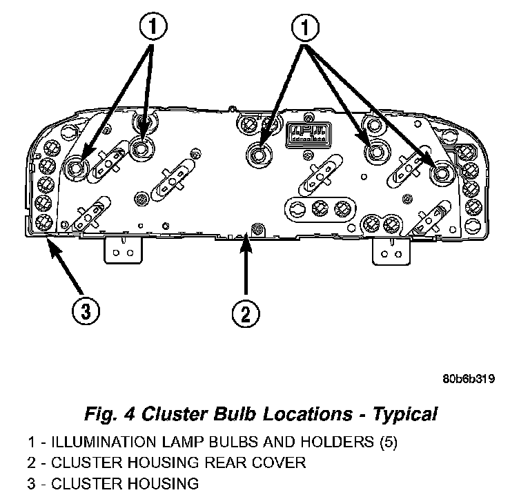
3. Turn the bulb holder counterclockwise about sixty degrees on the cluster electronic circuit board (Fig. 4).
4. Pull the bulb and bulb holder straight back to remove it from the bulb mounting hole in the cluster electronic circuit board.
Cluster Lens, Hood And Mask
1. Disconnect and isolate the battery negative cable.
2. Remove the instrument cluster from the instrument panel. Instrument Cluster Replacement
Fig.5 Instrument Cluster Components:
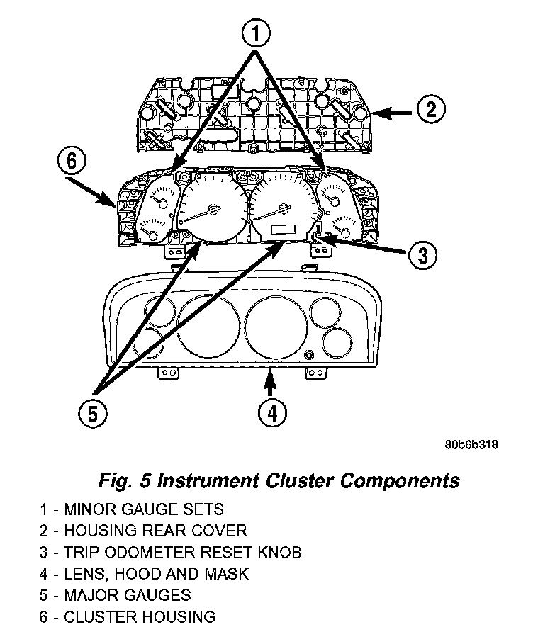
3. Work around the perimeter of the cluster housing to disengage each of the eight latches that secure the cluster lens, hood and mask unit to the cluster housing (Fig. 5).
4. Gently pull the cluster lens, hood and mask unit away from the cluster housing.
Cluster Housing Rear Cover
1. Disconnect and isolate the battery negative cable.
2. Remove the instrument cluster from the instrument panel. Instrument Cluster Replacement
Fig.6 Cluster Housing Rear Cover Screws:
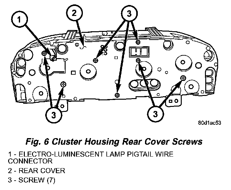
3. On models with a premium cluster only disconnect the electro-luminescent illumination lamp pigtail wire connector from the receptacle on the cluster electronic circuit board and disengage the pigtail wire from the integral routing clip on the rear cover (Fig. 6).
4. Remove the seven screws that secure the rear cover to the back of the cluster housing.
5. Disengage the eight latch features (four on top, four on the bottom) that secure the upper and lower edges of the rear cover to the top and bottom of the cluster housing.
6. Remove the rear cover from the back of the cluster housing.
ASSEMBLY
WARNING:
- ON VEHICLES EQUIPPED WITH AIRBAGS, DISABLE THE SUPPLEMENTAL RESTRAINT SYSTEM BEFORE ATTEMPTING ANY STEERING WHEEL, STEERING COLUMN, DRIVER AIRBAG, PASSENGER AIRBAG, SIDE CURTAIN AIRBAG, FRONT IMPACT SENSOR, SIDE IMPACT SENSOR, OR INSTRUMENT PANEL COMPONENT DIAGNOSIS OR SERVICE. DISCONNECT AND ISOLATE THE BATTERY NEGATIVE (GROUND) CABLE, THEN WAIT TWO MINUTES FOR THE SYSTEM CAPACITOR TO DISCHARGE BEFORE PERFORMING FURTHER DIAGNOSIS OR SERVICE. THIS IS THE ONLY SURE WAY TO DISABLE THE SUPPLEMENTAL RESTRAINT SYSTEM. FAILURE TO TAKE THE PROPER PRECAUTIONS COULD RESULT IN ACCIDENTAL AIRBAG DEPLOYMENT AND POSSIBLE PERSONAL INJURY.
- ON VEHICLES EQUIPPED WITH THE PREMIUM INSTRUMENT CLUSTER, THE CLUSTER CIRCUITRY PROVIDES AN ALTERNATING CURRENT TO SUPPLY POWER TO THE ELECTRO-LUMINES-CENT ILLUMINATION LAMP THROUGH A PIGTAIL WIRE AND CONNECTOR THAT IS ACCESSIBLE AT THE BACK OF THE CLUSTER HOUSING. USE PROPER PRECAUTIONS WHEN HANDLING THIS UNIT DURING DIAGNOSIS OR SERVICE TO AVOID ELECTRICAL SHOCK AND POSSIBLE PERSONAL INJURY.
Cluster Bulb
This procedure applies to each of the incandescent cluster illumination lamp or indicator bulb and bulb holder units. However, the illumination lamps and the indicators use different bulb and bulb holder unit sizes. They must never be interchanged.
CAUTION: Be certain that any bulb and bulb holder unit removed from the cluster electronic circuit board is reinstalled in the correct position. Always use the correct bulb size and type for replacement. An incorrect bulb size or type may overheat and cause damage to the instrument cluster, the electronic circuit board and/or the gauges.
1. Insert the bulb and bulb holder straight into the correct bulb mounting hole in the cluster electronic circuit board (Fig. 4).
2. With the bulb holder hilly seated against the cluster electronic circuit board, turn the bulb holder clockwise about sixty degrees to lock it into place.
3. Reinstall the instrument cluster onto the instrument panel. Instrument Cluster Replacement
4. Reconnect the battery negative cable.
Cluster Lens, Hood And Mask
1. Position the cluster lens, hood and mask unit over the face of the instrument cluster (Fig. 5). Be certain that the odometer/trip odometer switch button is inserted through the proper clearance holes in the mask and the lens.
2. Press firmly and evenly on the cluster lens, hood and mask unit to install it onto the cluster housing.
3. Work around the perimeter of the cluster housing to be certain that each of the eight latches that secure the cluster lens, hood and mask unit to the cluster housing is fully engaged.
4. Reinstall the instrument cluster into the instrument panel. Instrument Cluster Replacement
5. Reconnect the battery negative cable.
Cluster Housing Rear Cover
1. Position the rear cover onto the back of the cluster housing (Fig. 6).
2. Press firmly and evenly on the rear cover until each of the eight latches (four on top, four on the bottom) that secure the upper and lower edges of the rear cover to the top and bottom of the cluster housing are fully engaged.
3. Install and tighten the seven screws that secure the rear cover to the back of the cluster housing. Tighten the screws to 2 Nm (20 in. lbs.).
4. On models with a premium cluster only, reconnect the electro-luminescent illumination lamp pigtail wire connector to the receptacle on the cluster electronic circuit board and engage the pigtail wire under the integral routing clip on the rear cover.
5. Reinstall the instrument cluster onto the instrument panel. Instrument Cluster Replacement
6. Reconnect the battery negative cable.