Right Camshaft
CAMSHAFT(S) RIGHTREMOVAL
CAUTION: When the timing chain is removed and the cylinder heads are still installed, DO NOT forcefully rotate the camshafts or crankshaft independently of each other. Severe valve and/or piston damage can occur.
CAUTION: When removing the cam sprocket, timing chains or camshaft, Failure to use special tool 8350 will result in hydraulic tensioner ratchet over extension, Requiring timing chain cover removal to re-set the tensioner ratchet.
1. Remove the cylinder head covers.
2. Set engine to TDC cylinder # 1, camshaft sprocket V8 marks at the 12 o'clock position.
3. Mark one link on the secondary timing chain on both sides of the V8 mark on the camshaft sprocket to aid in installation.
CAUTION: Do not hold or pry on the camshaft target wheel for any reason, Severe damage will occur to the target wheel. A damaged target wheel could cause a vehicle no start condition.
4. Loosen but DO NOT remove the camshaft sprocket retaining bolt. Leave bolt snug against sprocket.
NOTE: The timing chain tensioners must be secured prior to removing the camshaft sprockets. Failure to secure tensioners will allow the tensioners to extend, requiring timing chain cover removal in order to reset tensioners.
CAUTION: Do not force wedge past the narrowest point between the chain strands. Damage to the tensioners may occur.
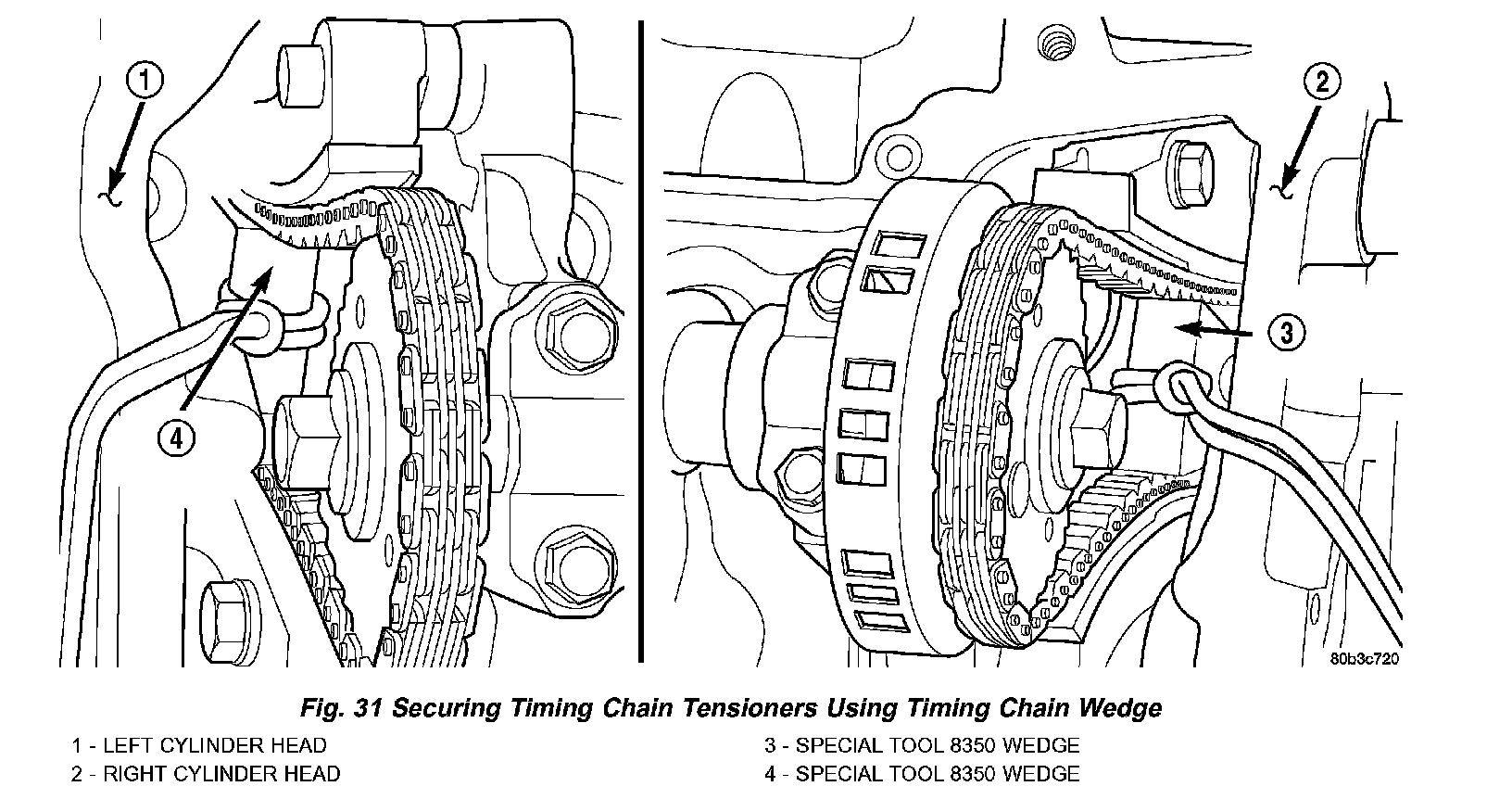
5. Position Special Tool 8350 timing chain wedge between the timing chain strands. Tap the tool to securely wedge the timing chain against the tensioner arm and guide (Fig. 31).
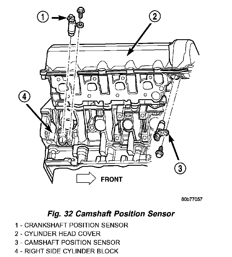
6. Remove the camshaft position sensor (Fig. 32).
NOTE: When gripping the camshaft, place the pliers on the tube portion of the camshaft only. Do not grip the lobes or the sprocket areas.
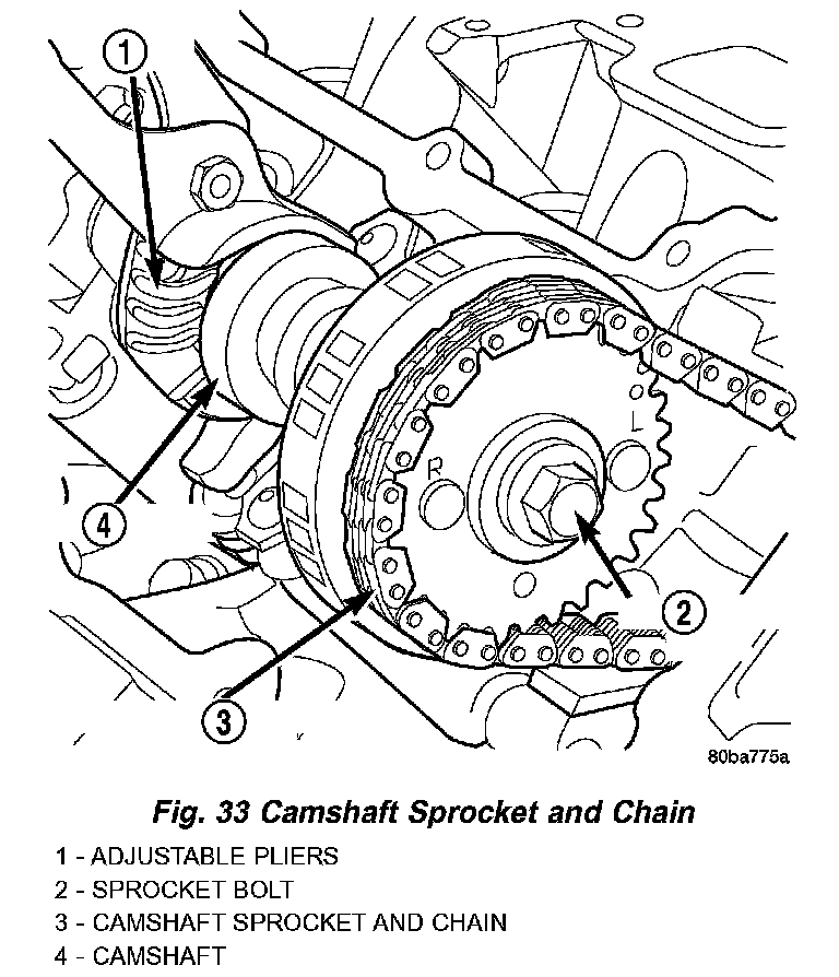
7. Hold the camshaft with adjustable pliers while removing the camshaft sprocket bolt and sprocket (Fig. 33).
8. Using the pliers, gently allow the camshaft to rotate 45° counter-clockwise until the camshaft is in the neutral position (no valve load).
9. Starting at the outside working inward, loosen the camshaft bearing cap retaining bolts 1/2 turn at a time. Repeat until all load is off the bearing caps.
CAUTION: DO NOT STAMP OR STRIKE THE CAMSHAFT BEARING CAPS. SEVERE DAMAGE WILL OCCUR TO THE BEARING CAPS.
NOTE: When the camshaft is removed the rocker arms may slide downward, mark the rocker arms before removing camshaft.
10. Remove the camshaft bearing caps and the camshaft.
INSTALLATION
1. Lubricate camshaft journals with clean engine oil.
NOTE: Position the right side camshaft so that the camshaft sprocket dowel is near the 10 o'clock position, This will place the camshaft at the neutral position easing the installation of the camshaft bearing caps.
2. Position the camshaft into the cylinder head.
3. Install the camshaft bearing caps, hand tighten the retaining bolts.
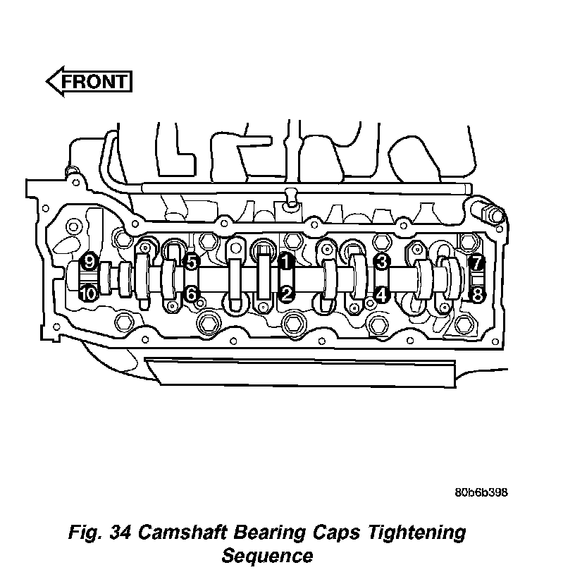
4. Working in 1/2 turn increments, tighten the bearing cap retaining bolts starting with the middle cap working outward (Fig. 34).
5. Torque the camshaft bearing cap retaining bolts to 11 Nm (100 in. lbs.).
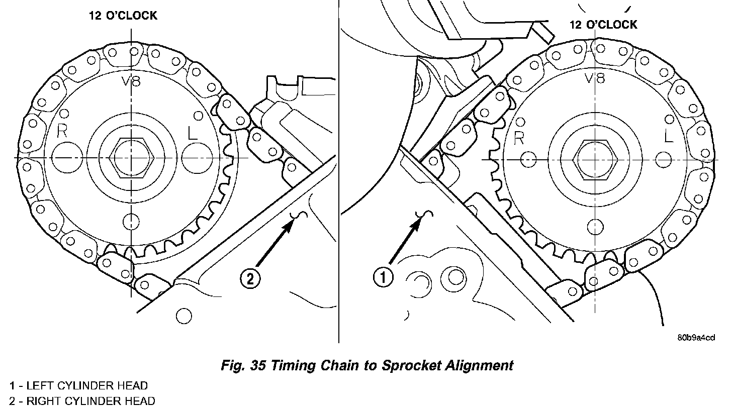
6. Position the camshaft drive gear into the timing chain aligning the V8 mark between the two marked chain links (Two links marked during removal) (Fig. 35).
NOTE: When gripping the camshaft, place the pliers on the tube portion of the camshaft only. Do not grip the lobes or the sprocket areas.
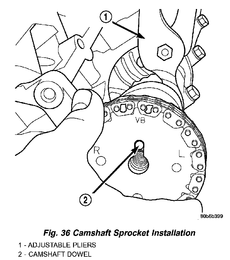
7. Using the adjustable pliers, rotate the camshaft until the camshaft sprocket dowel is aligned with the slot in the camshaft sprocket. Install the sprocket onto the camshaft (Fig. 36).
CAUTION: Remove excess oil from camshaft sprocket bolt. Failure to do so can cause bolt overtorque resulting in bolt failure.
8. Remove excess oil from camshaft sprocket bolt, then install the camshaft sprocket retaining bolt and hand tighten.
9. Remove timing chain wedge special tool 8350 (Fig. 31).
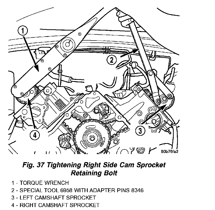
10. Using Special Tool 6958 spanner wrench with adapter pins 8346 (Fig. 37), torque the camshaft sprocket retaining bolt to 122 Nm (90 ft. lbs.).
11. Install the camshaft position sensor (Fig. 32).
12. Install the cylinder head cover.