Part 3 of 3
RADIOAvailable factory-installed radio receivers for this model include an AM/FM/cassette with CD changer control feature (RBB sales code), an AM/FM/CD/2-band graphic equalizer with CD changer control feature (RBK sales code), or an AM/FM/CD/cassette/2-band graphic equalizer (RBP sales code). All factory-installed radio receivers can communicate on the Programmable Communications Interface (PCI) data bus network through a separate wire harness connector. All factory-installed receivers are stereo Electronically Tuned Radios (ETR) and include an electronic digital clock function.
These radio receivers can only be serviced by an authorized radio repair station. See the latest Warranty Policies and Procedures for a current listing of authorized radio repair stations.
All vehicles are equipped with an Ignition-Off Draw (IOD) fuse that is removed when the vehicle is shipped from the factory. This fuse feeds various accessories that require battery current when the ignition switch is in the OFF position, including the clock. The IOD fuse is removed to prevent battery discharge during vehicle storage.
When removing or installing the IOD fuse it is important that the ignition switch be in the OFF position. Failure to place the ignition switch in the OFF position can cause the radio display to become scrambled when the IOD fuse is removed and replaced. Removing and replacing the IOD fuse again, with the ignition switch in the OFF position, will correct the scrambled display condition.
The IOD fuse should be checked if the radio or clock displays are inoperative. The IOD fuse is located in the Power Distribution Center (PDC). Refer to the fuse layout label on the underside of the PDC cover for IOD fuse identification and location.
The radio receiver operates on ignition switched battery current that is available only when the ignition switch is in the ON or Accessory positions. The electronic digital clock function of the radio operates on fused battery current supplied through the IOD fuse, regardless of the ignition switch position.
For more information on the features, setting procedures, and control functions for each of the available factory-installed radio receivers, refer to the owner 5 manual. For complete circuit diagrams, refer to the appropriate wiring information. The wiring information includes wiring diagrams, proper wire and connector repair procedures, details of wire harness routing and retention, connector pin-out information and location views for the various wire harness connectors, splices and grounds.
RADIO NOISE SUPPRESSION GROUND STRAP
Radio Frequency Interference (RFI) and ElectroMagnetic Interference (EMI) noise suppression is accomplished primarily through circuitry internal to the radio receivers. These internal suppression devices are only serviced as part of the radio receiver.
External suppression devices that are used on this vehicle to control RFI or EMI noise include the following:
- Radio antenna base ground
- Radio receiver chassis ground wire or strap
- Engine-to-body ground strap(s)
- Exhaust system-to-body and transmission ground strap (4.7L engines only)
- Resistor-type spark plugs
- Radio suppression-type secondary ignition wiring.
For more information on the spark plugs and secondary ignition components, refer to Ignition System in Ignition System.
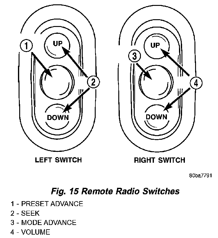
Fig.15 Remote Radio Switches:
REMOTE SWITCHES
Remote radio control switches are included on models equipped with the optional leather-wrapped steering wheel. The two rocker-type switch units are mounted in the upper spoke covers of the rear (instrument panel side) steering wheel trim cover. The switch unit on the left side is the seek switch and has seek up, seek down, and preset station advance switch functions. The switch unit on the right side is the volume control switch and has volume up, volume down, and mode advance switch functions.
The two remote radio switch units share a common steering wheel wire harness with the vehicle speed control switches. The steering wheel wire harness is connected to the instrument panel wire harness through the clockspring. (Refer to ELECTRICAL/RESTRAINTS/CLOCKSPRING - DESCRIPTION) for more information on this component.
For complete circuit diagrams, refer to the appropriate wiring information. The wiring information includes wiring diagrams, proper wire and connector repair procedures, details of wire harness routing and retention, connector pin-out information and location views for the various wire harness connectors, splices and grounds.
The six switches in the two remote radio switch units are normally open, resistor multiplexed momentary switches that are hard wired to the Body Control Module (BCM) through the clockspring. The BCM sends a five volt reference signal to both switch units on one circuit, and senses the status of all of the switches by reading the voltage drop on a second circuit.
When the BCM senses an input (voltage drop) from any one of the remote radio switches, it sends the proper switch status messages on the Programmable Communication Interface (PCI) data bus network to the radio receiver. The electronic circuitry within the radio receiver is programmed to respond to these remote radio switch status messages by adjusting the radio settings as requested. For diagnosis of the BCM or the PCI data bus, the use of a DRB scan tool and the proper Diagnostic Procedures are recommended.
For more information on the features and control functions for each of the remote radio switches, see the owner's manual in the vehicle glove box.
SPEAKER
Standard
The standard equipment speaker system includes speakers in six locations. One 6.4 centimeter (2.50 inch) diameter tweeter is installed on each end of the instrument panel top pad. One 15.2 by 22.9 centimeter (6 by 9 inch) full-range speaker is located in each front door. There is also one full-range 16.5 centimeter (6.5 inch) diameter full-range speaker located in each rear door.
Each of the two tweeters and four full-range speakers used in the standard speaker system is driven by the amplifier that is integral to the factory-installed radio receiver. For complete circuit diagrams, refer to the appropriate wiring information. The wiring information includes wiring diagrams, proper wire and connector repair procedures, details of wire harness routing and retention, connector pin-out information and location views for the various wire harness connectors, splices and grounds.
Premium
The optional premium speaker system features six Infinity model speakers in six locations. Each of the standard speakers is replaced with Infinity model speakers. One 6.4 centimeter (2.50 inch) diameter Infinity tweeter is installed on each end of the instrument panel top pad. One 15.2 by 22.9 centimeter (6 by 9 inch) Infinity woofer is located in each front door. There is also one full-range 16.5 centimeter (6.5 inch) diameter Infinity full-range speaker located in each rear door. The premium speaker system also includes an additional Infinity power amplifier. The total available power of the premium speaker system is about 180 watts.
The six Infinity speakers used in the premium speaker system are all driven by the radio receiver through an Infinity power amplifier. For complete circuit diagrams, refer to the appropriate wiring information. The wiring information includes wiring diagrams, proper wire and connector repair procedures, details of wire harness routing and retention, connector pin-out information and location views for the various wire harness connectors, splices and grounds.