Part 2 of 3
AMPLIFIERModels equipped with the Infinity premium speaker package have a separate power amplifier unit. This power amplifier is rated at 180 watts output. The power amplifier unit is mounted to the rear floor panel under the passenger side rear seat cushion. The power amplifier unit can be accessed for service by unlatching and tilting the passenger side rear seat cushion forward.
The power amplifier unit should be checked if there is no sound output noted from the speakers. For diagnosis of the power amplifier, (Refer to ELECTRICAL/AUDIO/SPEAKER - DIAGNOSIS AND TESTING). The power amplifier cannot be repaired or adjusted and, if faulty or damaged, the unit must be replaced.
The power amplifier is energized by a fused 12 volt output from the radio receiver whenever the radio is turned ON. The power amplifier receives the sound signal inputs for four speaker channels from the radio receiver, then sends the amplified speaker outputs for each of those channels to the six Infinity speakers. For complete circuit diagrams, refer to the appropriate wiring information. The wiring information includes wiring diagrams, proper wire and connector repair procedures, details of wire harness routing and retention, connector pin-out information and location views for the various wire harness connectors, splices and grounds.
Fig.5 Antenna Body And Cable:
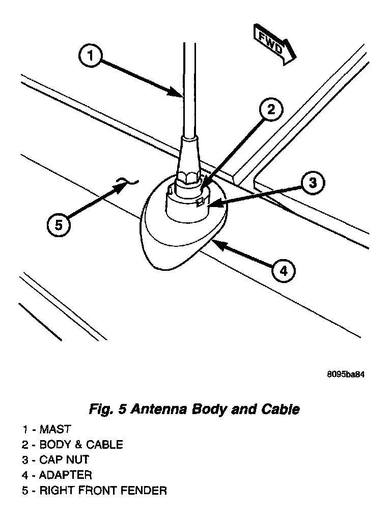
ANTENNA BODY & CABLE
The antenna body and cable is secured below the fender panel by the antenna cap nut through a mounting hole in the of the right front fender. The primary coaxial antenna cable is then routed beneath the fender sheet metal and through a entry hole in the right cowl side panel into the interior of the vehicle. Inside the vehicle, the primary coaxial cable is connected to a secondary instrument panel antenna coaxial cable with an in-line connector that is located behind the right kick panel. The secondary coaxial cable is then routed behind the instrument panel to the back of the radio.
The antenna body and cable connects the antenna mast to the radio. The radio antenna is an electromagnetic circuit component used to capture radio frequency signals that are broadcast by local commercial radio stations in both the Amplitude Modulating (AM) and Frequency Modulating (FM) frequency ranges. These electromagnetic radio frequency signals induce small electrical modulations into the antenna as they move past the mast. The antenna body transfers the weak electromagnetic radio waves induced into the rigid antenna mast into the center conductor of the flexible primary antenna coaxial cable. The braided outer shield of the antenna coaxial cable is grounded through both the antenna body and the radio chassis, effectively shielding the radio waves as they are conducted to the radio. The radio then tunes and amplifies the weak radio signals into stronger electrical signals in order to operate the audio system speakers.
Fig.7 Antenna Module:
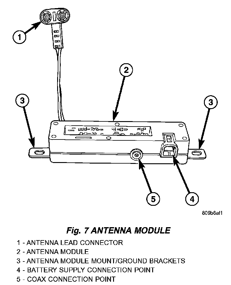
ANTENNA MODULE - EXPORT
The antenna module (Fig 7) is an electromagnetic circuit component designed to capture and enhance RF (Radio Frequency) signals in both the AM and FM broadcast bands. The antenna module is mounted to the right rear roof rail under the headliner. The modules mounting brackets also double as the ground circuit. The module has a two wire electrical connector that connects to the electric backlite integral radio antenna, located on the right rear quarter glass, a connector for the radio coax cable and a connector for battery voltage.
The antenna module receives both AM and FM radio signals supplied by the side window integral radio antenna system and selectively amplifies them while at the same time avoiding unusable or unwanted signals. The amplified signal is then sent through the body length coax cable to the radio input.
CD CHANGER
A factory-installed Compact Disc (CD) changer featuring a ten-CD magazine is an available option on this model when it is also equipped with the premium speaker package and a radio receiver including the CD controls feature. The CD changer is mounted in the cargo area of the passenger compartment on the right rear quarter panel.
The CD changer is connected to a take out from the right body wire harness and receives both ground and radio-switched battery current through the radio receiver. The controls on the radio receiver operate the CD changer through messages sent over the Programmable Communications Interface (PCI) data bus network. The two-channel audio outputs of the CD changer are hard wired back to the radio receiver, which then outputs the signal through four channels to the power amplifier. For diagnosis of the messaging functions of the radio receiver and the CD changer, or of the PCI data bus, a DRB scan tool and the proper Diagnostic Procedures are required.
The CD changer can only be serviced by an authorized radio repair station. See the latest Warranty Policies and Procedures for a current listing of authorized radio repair stations.
The CD changer will only operate when the ignition switch is in the ON or Accessory positions, and the radio is turned ON. For more information on the features, loading procedures and radio control functions for the operation of the CD changer, see the owner's manual in the vehicle glove box.
QUARTER GLASS INTEGRAL ANTENNA - EXPORT
The integral radio antenna element is bonded to the right rear quarter glass and is replaced with the glass assembly only.
The integral antenna receives RF (Radio Frequencies) and sends them to the antenna module for amplification.