Part 2 of 2
Fig.9 Siren Remove/Install:
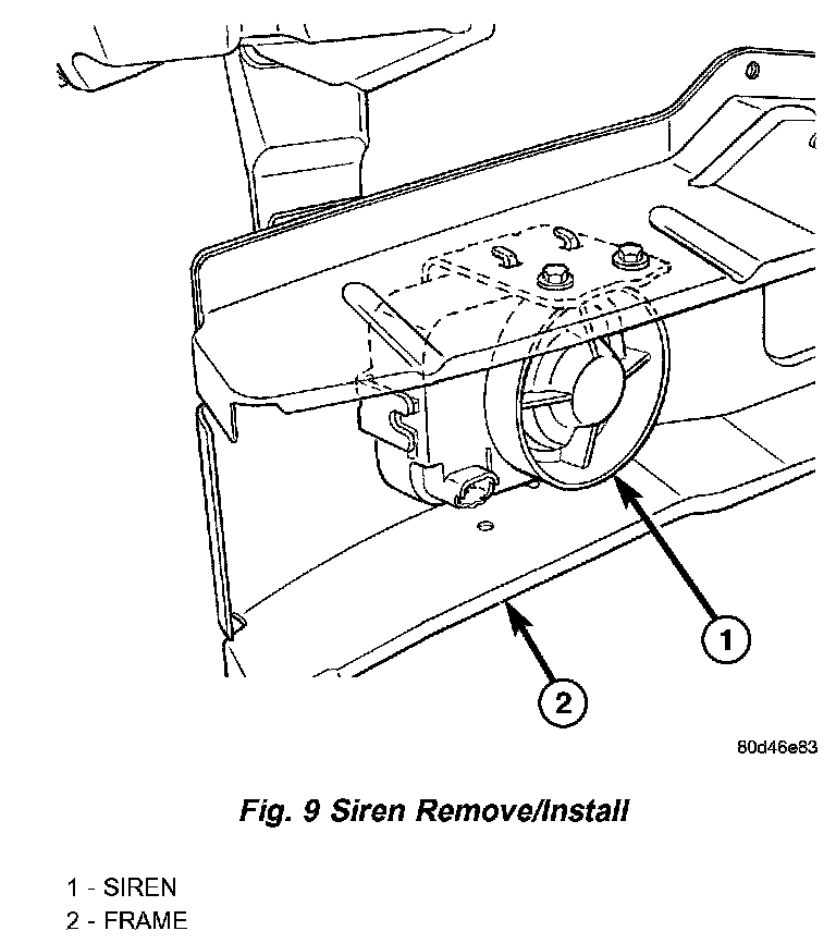
SIREN
An alarm siren module is part of the premium version of the Vehicle Theft Alarm (VTA) in the Vehicle Theft Security System (VTSS). The premium version of the VTA is only available in vehicles built for certain markets, where the additional features offered by this system are required. The alarm siren module is located in the right front frame rail. This unit is designed to provide the audible alert requirements for the premium VTA.
The alarm siren module consists of microprocessor, the siren, and a nickel metal hydride backup battery. All of the alarm module components are protected and sealed within the housing.
The alarm siren module cannot be repaired or adjusted and, if faulty or damaged, it must be replaced.
The microprocessor within the alarm siren module provides the siren unit features and functions based upon internal programming and arm and disarm messages received from the Intrusion Transceiver Module (ITM) over a dedicated serial bus communication circuit. The alarm siren module will self-detect problems with its internal and external power supply and communication circuits, then send messages indicating the problem to the ITM upon receiving a request from the ITM. The ITM will store a Diagnostic Trouble Code (DTC) for a detected alarm siren module fault that can be retrieved with the DRB III scan tool over the Programmable Communications Interface (PCI) data bus.
When the premium version of the Vehicle Theft Alarm (VTA) is armed, the alarm siren module continuously monitors inputs from the ITM for messages to sound its siren and enters its auto-detect mode. While in the auto-detect mode, if the alarm siren module detects that its power supply or communication circuits are being tampered with or have been sabotaged, it will sound an alarm and continue to operate through its on-board backup battery If the arm siren module is in its disarmed mode when its power supply or communication circuits are interrupted, the siren will not sound. The alarm module will also notify the ITM when the backup battery requires charging, and the ITM will send a message that will allow the backup battery to be charged through the battery voltage and ground circuits to the alarm module only when the ignition switch is in the ON position and the engine is running. This will prevent the charging of the alarm backup battery from depleting the charge in the main vehicle battery while the vehicle is not being operated.
The alarm siren module receives battery voltage through a fuse in the Power Distribution Center (PDC), and is grounded to the chassis. These connections allow the alarm siren module to remain operational, regardless of the ignition switch position. The hard wired inputs and outputs for the alarm siren module may be diagnosed and tested using conventional diagnostic tools and procedures. However, conventional diagnostic methods will not prove conclusive in the diagnosis of the internal circuitry or the backup battery of the alarm siren module, the ITM, the serial bus communication line, or the message inputs to and outputs from the alarm siren module. The most reliable, efficient, and accurate means to diagnose the alarm siren module, the ITM, the serial bus communication line, and the electronic message inputs to and outputs from the alarm siren module requires the use of a DRB III scan tool. Refer to the appropriate diagnostic information.
SKIS INDICATOR LAMP
A Sentry Key Immobilizer System (SKIS) indicator lamp is standard equipment on all instrument clusters, but is only functional on vehicles equipped with the optional SKIS. The amber SKIS indicator lamp is located to the right of the oil pressure gauge.
The Sentry Key Immobilizer System (SKIS) indicator lamp gives an indication to the vehicle operator of the status of the SKIS. This lamp is controlled by a transistor on the instrument cluster circuit board based upon messages received by the cluster from the Sentry Key Immobilizer Module (SKIM) over the Programmable Communications Interface (PCI) data bus. The SKIS indicator lamp bulb receives battery current on the instrument cluster circuit board through the fused ignition switch output (st-run) circuit whenever the ignition switch is in the ON or Start positions. The lamp bulb only illuminates when it is provided a path to ground by the instrument cluster transistor. The instrument cluster will turn ON the SKIS indicator lamp for the following reasons:
- Bulb Test - Each time the ignition switch is turned to the ON position, the SKIM tells the cluster to illuminate the lamp for about three seconds.
- SKIS Lamp-ON Message - Each time the cluster receives a SKIS lamp-on message from the SKIM, the lamp will be illuminated. The lamp can be flashed ON and OFF ON , or illuminated solid, as dictated by the message from the SKIM. The lamp remains illuminated until the cluster receives a lamp-off message from the SKIM or until the ignition switch is turned to the OFF position, whichever occurs first.
- Actuator Test - Each time the cluster is put through the actuator test, the lamp will be turned ON for the duration of the test to confirm the functionality of the lamp and the cluster.
The SKIM performs a self-test each time the ignition switch is turned to the ON position to decide whether the system is in good operating condition. The SKIM then sends a message to the instrument cluster. If the SKIS indicator lamp fails to light during the bulb test, replace the bulb. For further diagnosis of the SKIS indicator lamp or the instrument cluster circuitry that controls the lamp, refer to Instrument Cluster Diagnosis and Testing. If the instrument cluster turns ON the SKIS indicator lamp after the bulb test, either solid or flashing, it indicates that a SKIS malfunction has occurred or that the SKIS is inoperative. For proper diagnosis of the SKIS, the PCI data bus, or the message inputs to the instrument cluster that control the SKIS indicator lamp, a DRB III scan tool and the appropriate diagnostic information are required.
Sentry Key Immobilizer Transponder:
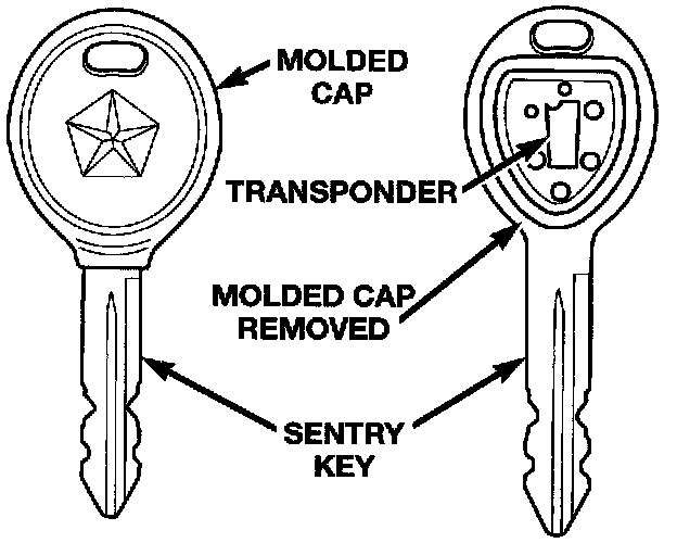
TRANSPONDER KEY
Each ignition key used in the Sentry Key Immobilizer System (SKIS) has an integral transponder chip. Ignition keys with this feature can be readily identified by a gray rubber cap molded onto the head of the key, while conventional ignition keys have a black molded rubber cap. The transponder chip is concealed beneath the molded rubber cap, where it is molded into the head of the metal key. Each new Sentry Key has a unique transponder identification code permanently programmed into it by the manufacturer. The Sentry Key transponder if faulty or damaged, must be replaced.
When the ignition switch is turned to the ON position, the Sentry Key Immobilizer Module (SKIM) communicates through its antenna with the Sentry Key transponder using a Radio Frequency (RF) signal. The SKIM then waits for a RF response from the transponder through the same antenna. The Sentry Key transponder chip is within the range of the SKIM transceiver antenna ring when it is inserted into the ignition lock cylinder. The SKIM determines whether a valid key is present in the ignition lock cylinder based upon the response from the transponder. If a valid key is detected, that fact is communicated by the SKIM to the Powertrain Control Module (PCM) over the Programmable Communications Interface (PCI) data bus, and the PCM allows the engine to continue running. If the PCM receives an invalid key message, or receives no message from the SKIM over the PCI data bus, the engine will be disabled after about two seconds of operation. The ElectroMechanical Instrument Cluster (EMIC) will also respond to the invalid key message on the PCI data bus by flashing the SKIS indicator ON and OFF.
Each Sentry Key has a unique transponder identification code permanently programmed into it by the manufacturer. Likewise, the SKIM has a unique Secret Key code programmed into it by the manufacturer. When a Sentry Key is programmed into the memory of the SKIM, the SKIM stores the transponder identification code from the Sentry Key, and the Sentry Key learns the Secret Key code from the SKIM. Once the Sentry Key learns the Secret Key code of the SKIM, it is permanently stored in the memory of the transponder. Therefore, once a Sentry Key has been programmed to a particular vehicle, it cannot be used on any other vehicle.
VTSS INDICATOR
The Vehicle Theft Security System (VTSS) indicator consists of a red Light-Emitting Diode that is mounted and integral to the automatic headlamp light sensor photo diode unit, which is located on the top of the instrument panel. The remainder of the housing including the mount and the electrical connection are concealed beneath the instrument panel top cover.
The VTSS indicator cannot be adjusted or repaired the entire automatic headlamp light sensor/VTSS indicator must be replaced.
The Vehicle Theft Security System (VTSS) indicator gives a visible indication of the VTSS arming status. One side of Light-Emitting Diode (LED) in the VTSS indicator is connected to unswitched battery current through a fused B(+) circuit and a fuse in the Junction Block (JB). The other side of the LED is hard wired to the Body Control Module (BCM), which controls the operation of the VTSS indicator by pulling this side of the LED circuit to ground. When the VTSS arming is in progress, the BCM will flash the LED rapidly ON and OFF for about fifteen seconds. When the VTSS has been successfully armed, the BCM will flash the LED ON and OFF continually at a much slower rate until the VTSS has been disarmed. The VTSS indicator can be diagnosed using conventional diagnostic tools and methods.