Automatic Zone Control (AZC)
ALLDATA Editor's Note:The AZC system is diagnosed using the Monitor Current Parameters and Output Circuit/Actuator tests only. There are no trouble code driven test procedures provided by DaimlerChrysler for this system.
AUTOMATIC ZONE CONTROL SYSTEM
The Automatic Zone Control (AZC) control module has a system self-diagnostic mode which continuously monitors various parameters during normal system operation. If a system fault is detected a current and historical fault is recorded. When the current fault is cleared the historical fault remains until reset (manually or automatically) Both the current and historical fault codes can be accessed through either the front panel or over the Programmable Communications Interface (PCI) bus using a DRBIII scan tool and the proper Diagnostic Procedures manual.
The AZC control module is capable of three different types of self-diagnostic tests as follows:
- Fault Code Tests
- Input Circuit Tests
- Output Circuit/Actuator Tests
The information that follows describes:
- How to read the self-diagnostic display
- How to enter the AZC control module self-diagnostic test mode
- How to select the self-diagnostic test types
- How to perform the different tests
ENTERING THE AZC SELF-DIAGNOSTIC MODE
To enter the AZC self-diagnostic mode perform the following:
1. Depress the A/C and Recirc buttons at the same time and hold. Rotate the left temperature control knob clockwise (CW) one detent.
2. If you continue to hold the A/C and Recirc buttons depressed the AZC control module will perform a Segment Test of the vacuum fluorescent (VF) display. In the Segment Test you should see all of the display segments illuminate as long as both buttons are held. If a display segment fails to illuminate the vacuum fluorescent display is faulty and the heater-A/C control must be replaced.
3. After viewing the Segment Test release the A/C and Recirc buttons and the display will clear momentarily. If a 0 is displayed, then no faults are set in the system. Should there be any faults either "current" or "historical" all fault codes will be displayed in ascending numerical sequence (note no effort is made to display fault codes in chronological order) Each fault code is displayed for one second before the next code is displayed. Once all fault codes have been displayed the system will then repeat the fault code numbers. This will continue until the left side set temperature control is moved at least one detent position in the CW direction or the ignition is turned "OFF".
FAULT CODE TESTS
Fault codes are two-digit numbers that identify a circuit that is malfunctioning. There are two different kinds of fault codes.
- Current Fault Codes - Current means the fault is present right now. There are two types of current faults: input faults and system faults.
- Historical Fault Codes - Historical or stored means that the fault occurred previously but is not present right now. A majority of historical fault codes are caused by intermittent wire harness or wire harness connector problems.
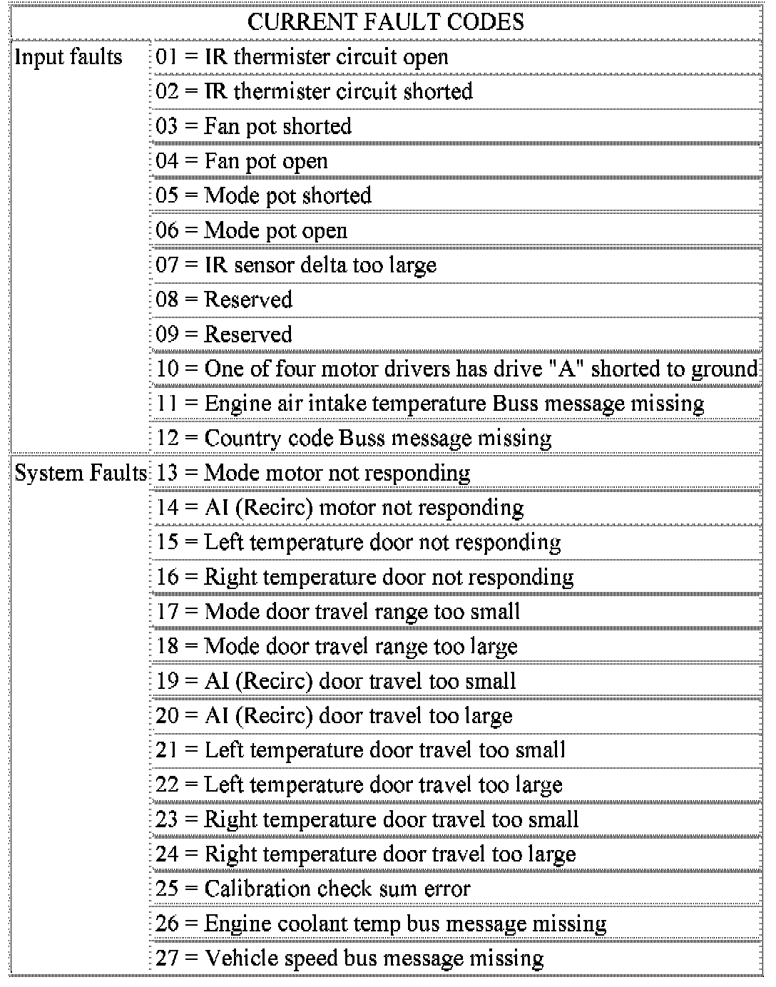
Current Fault Codes 01-27:
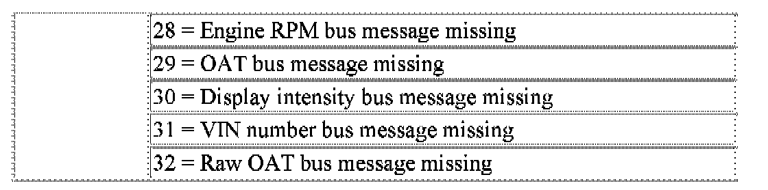
Current Fault Codes 28-32:
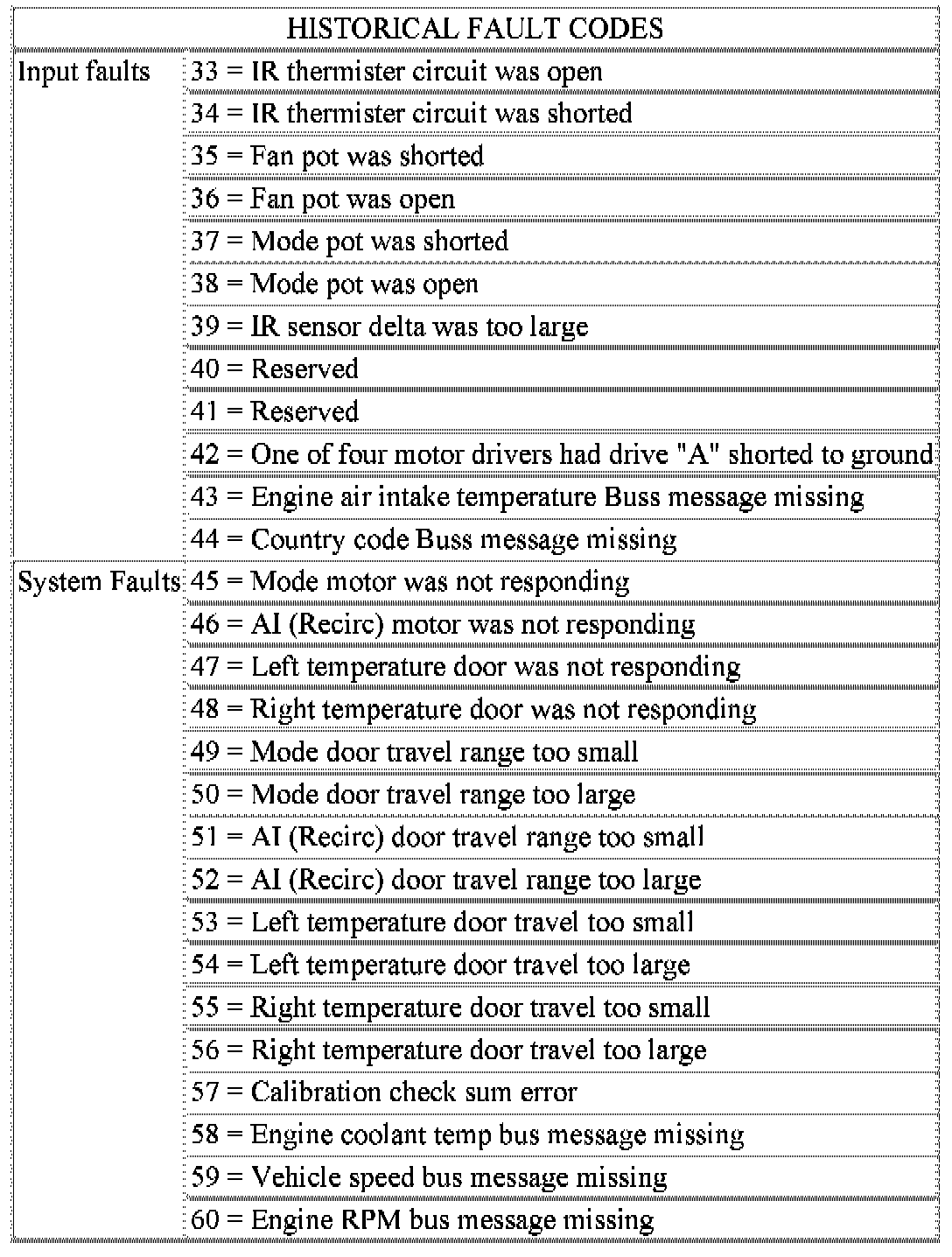
Historical Fault Codes 33-60:
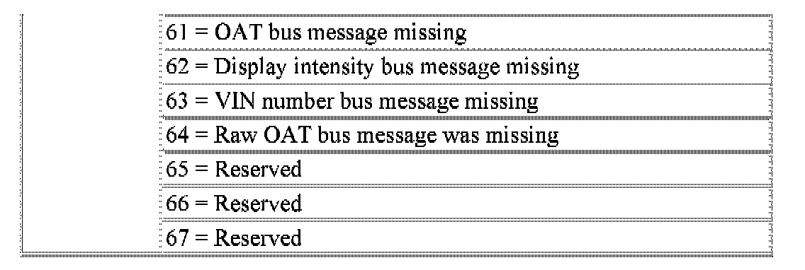
Historical Fault Codes 61-67:
NOTE: A battery disconnect Will erase all faults stored in Random Access Memory (RAM) of the AZC control module. It is recommended that all faults be recorded before they are erased.
RETRIEVING FAULT CODES
1. To begin the fault code tests depress the A/C and Recirc buttons at the same time and rotate the left temperature control knob clockwise (CW) one detent then release the push-button.
2. If there are no fault codes, the "00" display value Will remain in the VF window. Should there be any codes each will be displayed for one second in ascending numerical sequence (note: no effort is made to display faults in the order they occurred) The left side set temperature display will be blanked and the right side set temperature display will indicate current and historical codes (8 historical max) presently active. Once all codes have been displayed the system will repeat the fault code numbers. This will continue until the left side set temperature control is moved at least one detent position in either direction by pressing both the A/C and Recirc buttons at the same time or the ignition is turned off. Record all of the fault codes then see the Current and Historical Fault Code charts for the descriptions.
CLEARING FAULT CODES
Current faults cannot be electronically cleared. Repair must be made to the system to eliminate the fault causing code. Historical fault codes can be cleared manually or automatically. To clear a historical fault manually depress and hold either the A/C or Recirc button for at least three seconds while the display is in the fault code mode of operation. Historical fault codes are cleared automatically when the corresponding current fault code has been cleared and has remained cleared for a number of ignition cycles. The faults have been cleared when two horizontal bars appear in the Test Selector display.
EXITING SELF-DIAGNOSTIC MODE
The self-diagnostic mode can be exited by pressing both the A/C and Recirc buttons at the same time or turning off the ignition.
MONITOR CURRENT PARAMETERS
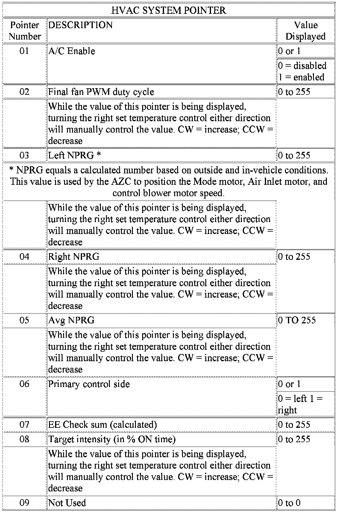
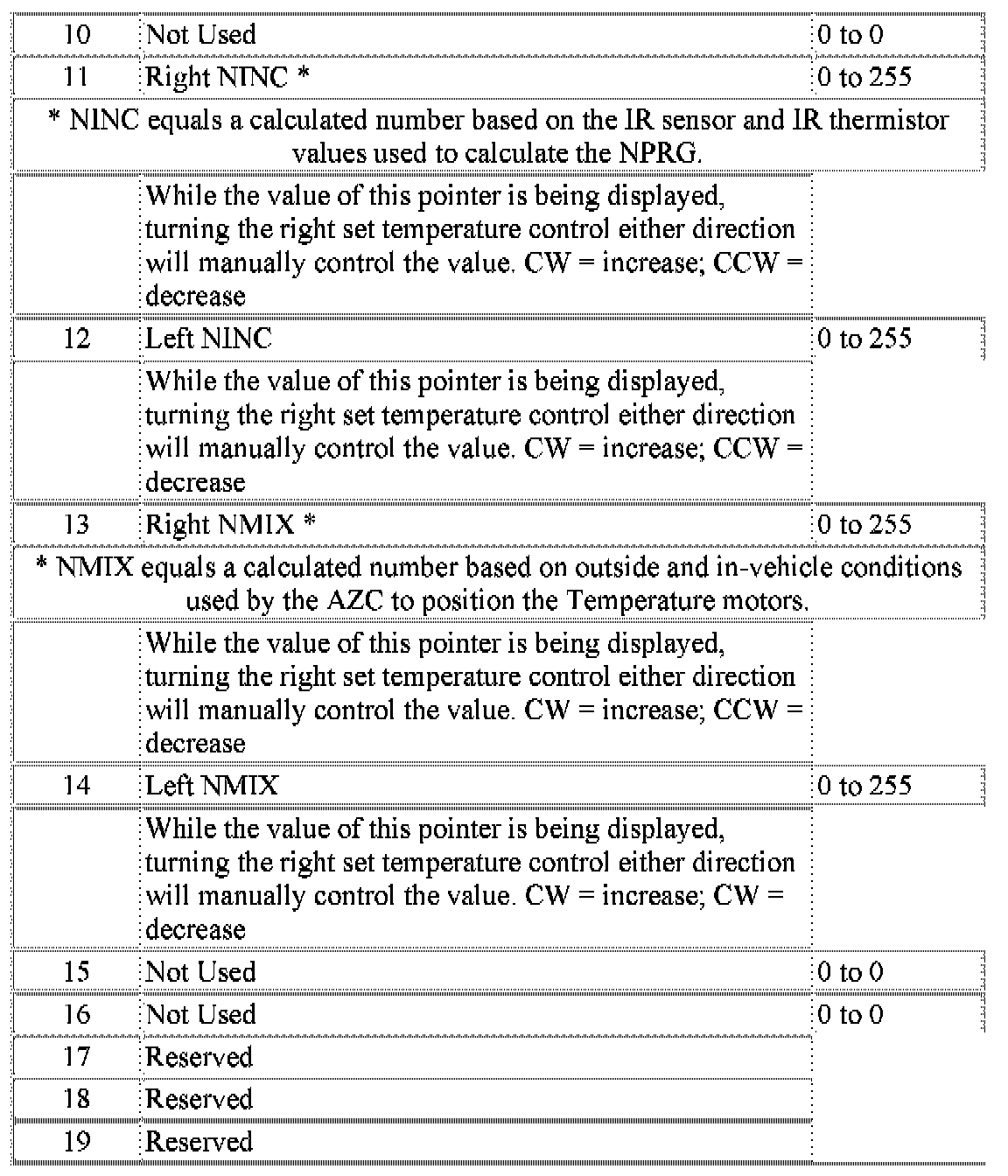
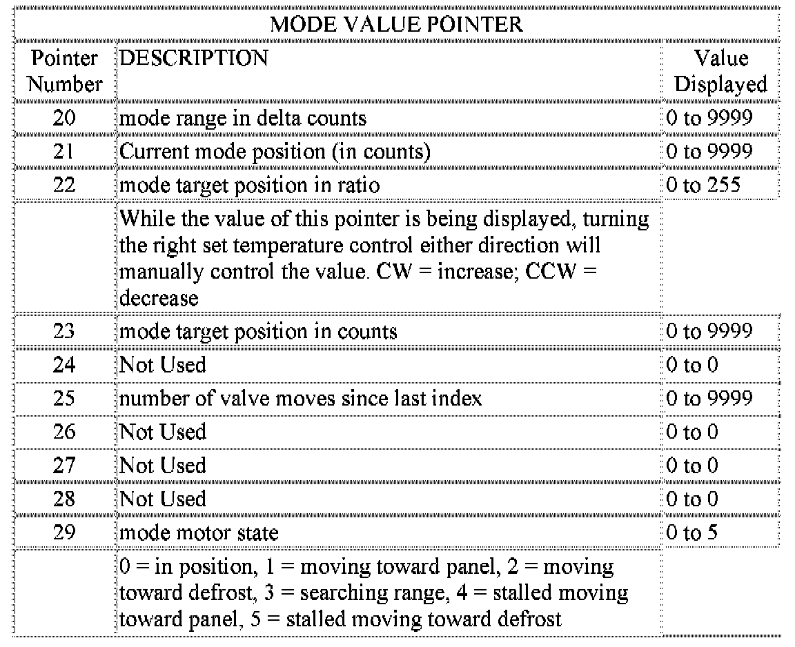
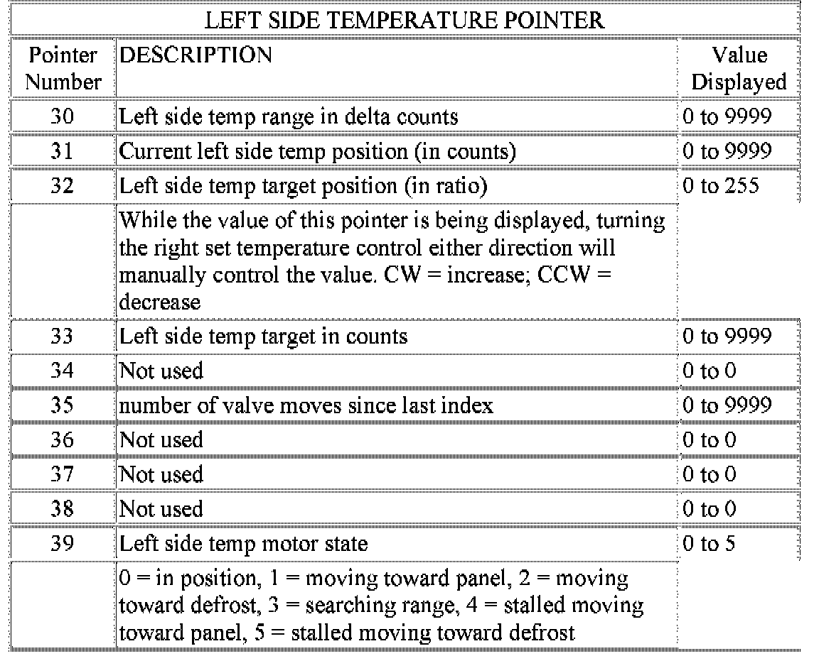
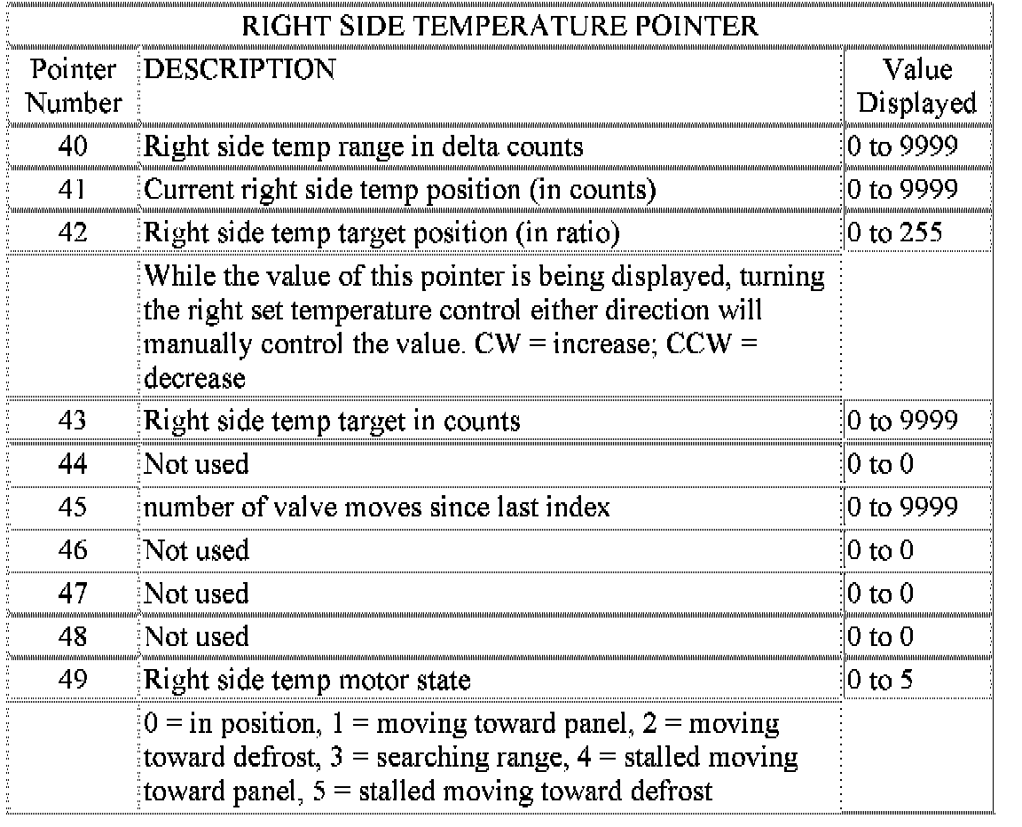
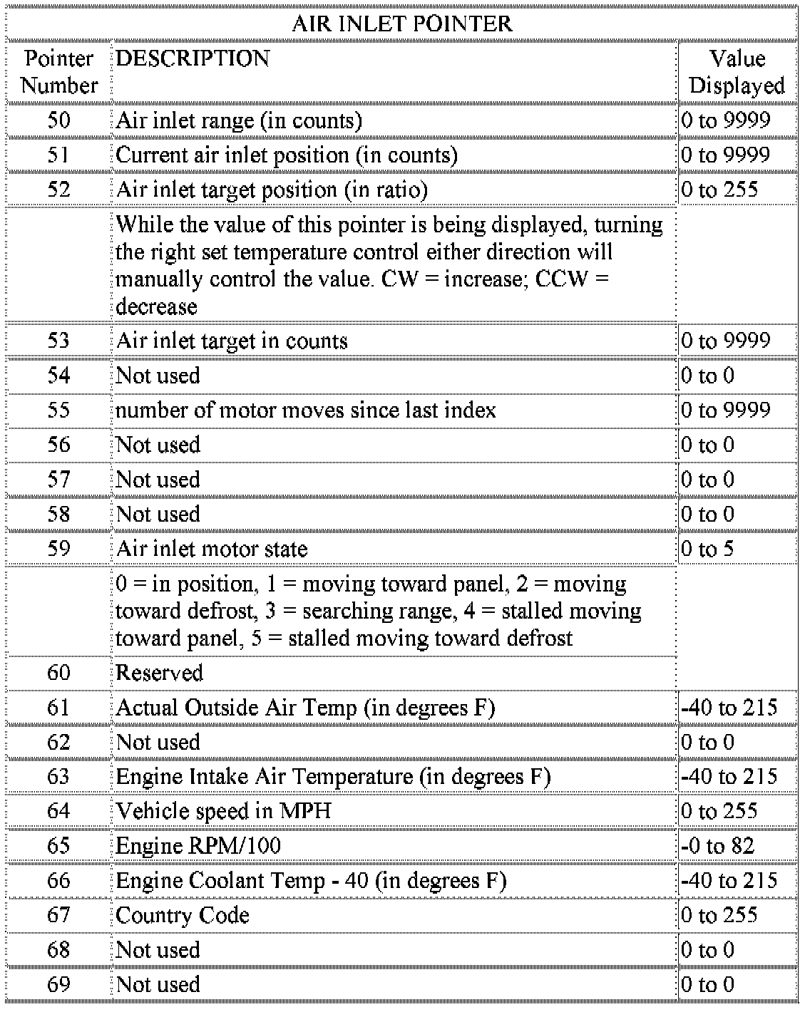
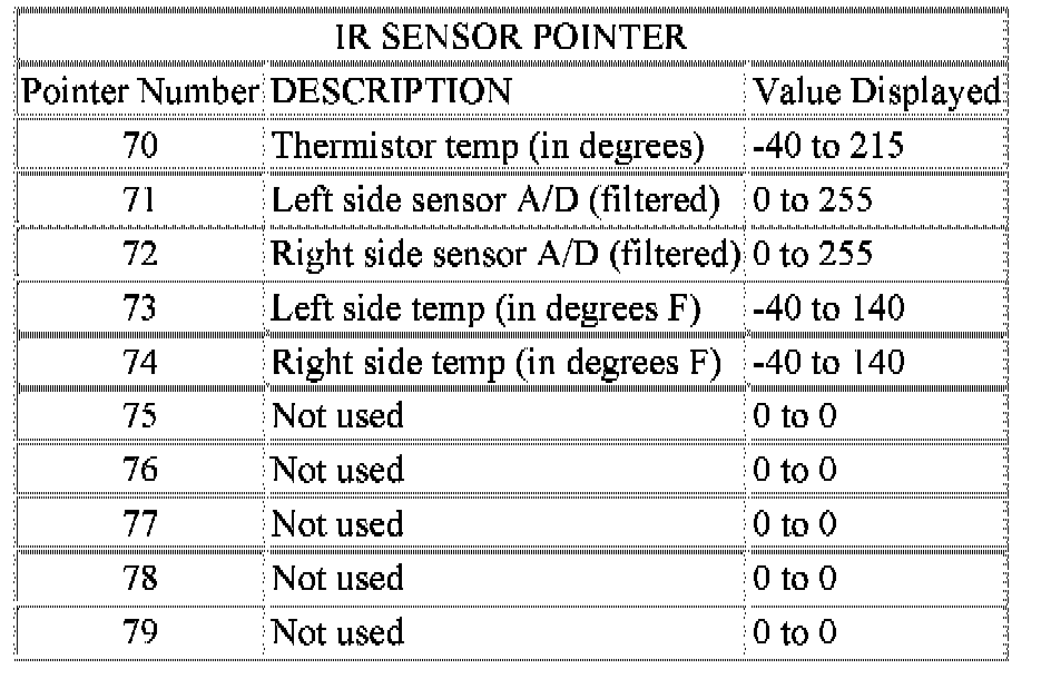
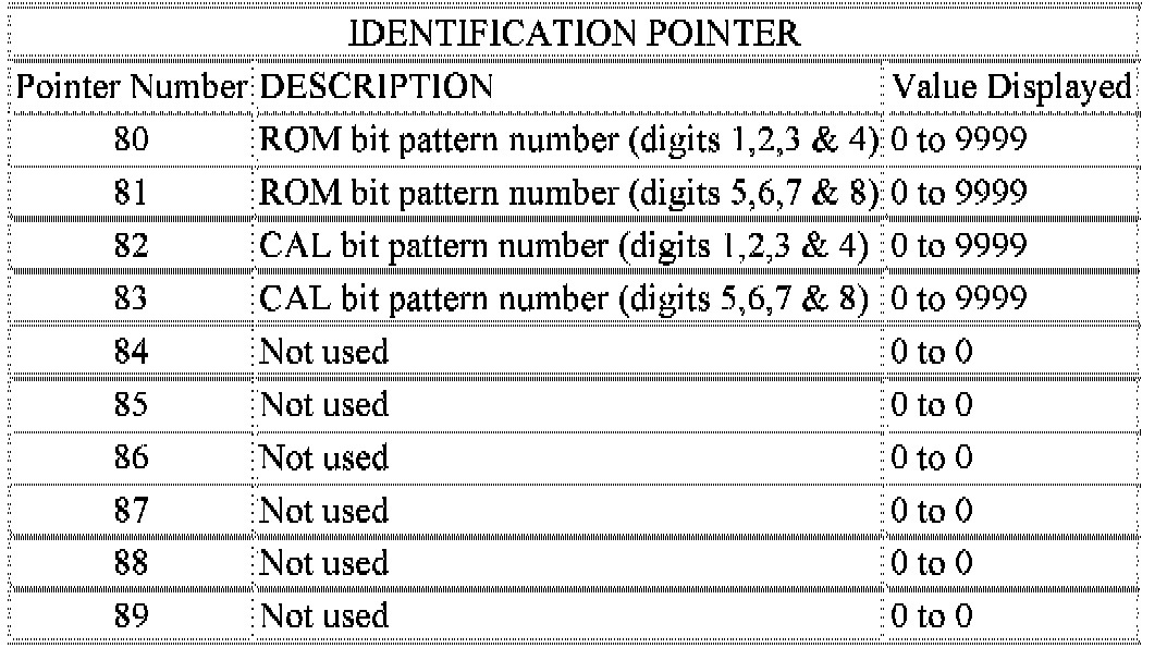
While in the display fault code mode of operation current system parameters can also be monitored and/or forced. Rotating the left side set temperature control clockwise will increase the pointer number while rotating the control counter clockwise will decrease the pointer number. Rotating the right set temperature control will have no impact on pointer value or the value of the parameter being monitored. Once the desired pointer number has been selected pressing either the AC or Recirc buttons will display the current value of the selected parameter. The right side set temperature display is only capable of displaying only values ranging from 0 to 99, the left side set temperature display is used for values greater than 99. If the value is less than 99, the left side set temperature display remains blanked. While a parameter is being overridden the system will continue to function normally except for the parameter which is being manually controlled.
For values < 0 the "G" segment in the left side set temperature Most Significant Digit (MSD)(or left-most number in the pair) will be used to indicate a negative number. For values between -01 to -99 the Least Significant Digit (LSD)(or right-most number of the pair) in the left side set temperature will remain blank. System control of parameter being displayed can be overridden by rotating the right set temperature control in either direction. Rotating the right temperature control in the CW direction~ the selected parameter value is overridden and incremented beginning at the value which was being displayed. Rotating the right temperature control in the CCW direction the selected parameter value is overridden and decremented beginning at the value which was being displayed. The rate at which incrementing and decrement occurs is one unit value per set temperature detent position.
HVAC System Pointer 01-09:
HVAC System Pointer 10-19:
Mode Value Pointer 20-29:
Left Side Temperature Pointer 30-39:
Right Side Temperature Pointer 40-49:
Air Inlet Pointer 50-69:
IR Sensor Pointer 70-79:
Identification Pointer 80-89:
OUTPUT CIRCUIT/ACTUATOR TESTS
In the Output Circuit/Actuator Test mode the output circuits can be viewed monitored overridden~ and tested. If a failure occurs in an output circuit test the circuit by overriding the system. Test the actuator through its full range of operation.
1. To begin the Output Circuit/Actuator Tests you must be in the Select Test mode.
2. With a "00" value displayed in the Test Selector and no stick man turn the rotary temperature control knob until the test number you are looking for appears in the Test Selector display. See the Circuit Testing charts for a listing of the test numbers test items test types system tested and displayed values.
3. To see the output value depress the A/C or Recirc button. The values displayed will represent the output from the AZC control module.
4. To enter the actuator test depress the A/C or Recirc button. Then rotate the right temperature set knob to the desired position.