Preliminary Diagnosis
- If indicators operate but all gauges are inoperative, go to next step. If all gauges and indicators are inoperative, go to step 5
.
- Remove and inspect fuse No. 16 (15-amp) from power distribution center. If fuse is okay, go to next step. If fuse is blown, repair short to ground in Pink wire between instrument cluster and power distribution center. Replace fuse.
- Measure voltage between ground and power side of fuse No. 16. If battery voltage is present, go to next step. If battery voltage is not present, repair open in power distribution circuits. See POWER DISTRIBUTION article in WIRING DIAGRAMS.
- Turn ignition switch to OFF position. Disconnect negative battery cable. Remove instrument cluster. See INSTRUMENT CLUSTER
under REMOVAL & INSTALLATION. Connect negative battery cable. Measure voltage between ground and terminal No. 9 (Pink wire) at instrument cluster harness connector C1. If battery voltage is present, install instrument cluster and perform ACTUATOR TEST
. If battery voltage is not present, repair open in Pink wire between fuse No. 16 in power distribution center and instrument cluster.
- Remove and inspect fuse No. 9 (10-amp) from junction block. If fuse is okay, go to next step. If fuse is blown, repair short to ground in White/Black wire between instrument cluster and junction block. Replace fuse.
- Turn ignition switch to ON position. Measure voltage between ground and power side of fuse No. 9. If battery voltage is present, go to next step. If battery voltage is not present, repair open in Dark Blue wire between ignition switch and junction block.
- Apply parking brake and observe instrument cluster BRAKE warning indicator. If warning indicator is on, go to next step. If warning indicator is off, go to step 9
.
- Turn ignition switch to OFF position. Turn parking lights on and rotate headlight switch rheostat to brighten cluster illumination. If cluster illumination is on, perform ACTUATOR TEST
. If cluster illumination is off, go to step 10
.
- Turn ignition switch to OFF position. Disconnect negative battery cable. Remove instrument cluster. See INSTRUMENT CLUSTER
under REMOVAL & INSTALLATION. Connect negative battery cable. Turn ignition switch to ON position. Measure voltage between ground and terminal No. 8 (White/Black wire) at instrument cluster harness connector C1. See Fig 1
. If battery voltage is present, perform ACTUATOR TEST
. If battery voltage is not present, repair open in White/Black wire between instrument cluster and junction block.
- Remove instrument cluster. See INSTRUMENT CLUSTER
under REMOVAL & INSTALLATION. Check continuity between ground and terminal No. 6 (Black/Light Green wire) at instrument cluster harness connector C1. Check continuity between ground and terminal No. 9 (Black/Light Green wire) at instrument cluster harness connector C2. If continuity exists at all terminals, perform ACTUATOR TEST
. If continuity does not exist at any terminal, repair short to ground in Black/Light Green wire between instrument cluster and ground point. Ground point is located near headlight switch.
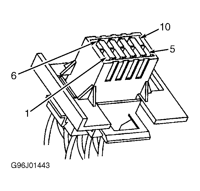 Courtesy of CHRYSLER CORP.