All Except With CV Joint
- Check condition of springs, engine and transmission mounts. Ensure all mounting fasteners are tight. To ensure proper riding height, fuel tank should be full and vehicle should be empty of cargo. Raise and support vehicle so suspension bears weight of vehicle and wheels can rotate freely.
- Rotate drive shaft so transmission/transfer case output yoke bearing cap is facing downward. See Fig 1
. Remove external clips from "U" joint cap bore. Ensure bearing cap is clean. Place Inclinometer (7663) on bearing cap in line with shaft. Center bubble in sight glass. Record measurement. This measurement is output yoke angle "A".
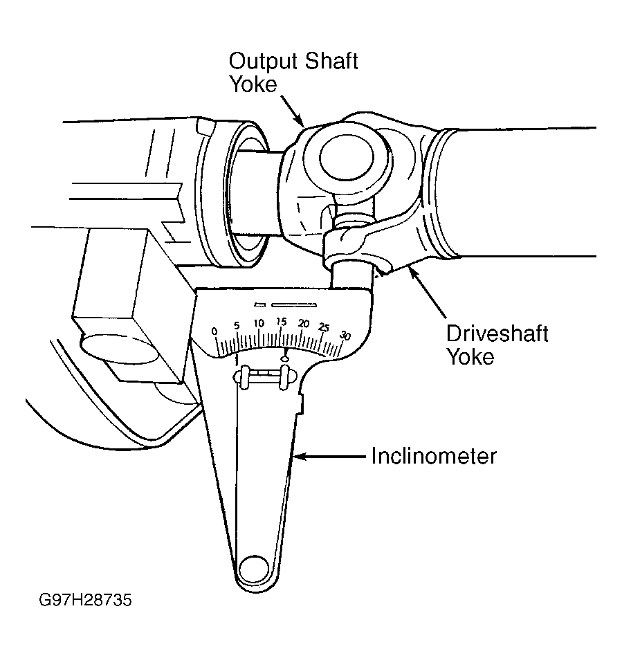 Courtesy of CHRYSLER CORP.
- Rotate drive shaft 90 degrees. Place inclinometer on drive shaft yoke bearing, in line with shaft. Center bubble in sight glass. Record measurement. This measurement is driveshaft angle "C". Subtract smaller figure from larger figure ("C" minus "A") to obtain transmission output operating angle.
- Rotate drive shaft 90 degrees. Place inclinometer at rear of drive shaft on pinion yoke bearing, in line with shaft. Center bubble in sight glass. Record measurement. This measurement is input yoke angle "B". Subtract smaller figure from larger figure ("C" minus "B") to obtain axle input operating angle.
- Compare transmission output operating angle to axle input operating angle. Subtract smaller figure from larger figure. The figure obtained is the amount of "U" joint cancellation.
- Ensure drive shaft angles meet the following conditions:
- Cancellation of "U" joint operating angles is within one degree.
- Each operating angle is less than 3 degrees.
- Minimum continuous operating driveshaft angle of 1/2 degree.