Removal (Instrument Pack Assembly & Printed Circuit)
- After disconnecting battery ground, remove driver's side dash liner securing screws, release securing clip and remove liner. Release steering column clamp, fully extend steering wheel and retighten clamp.
- Remove instrument pack assembly securing screws and disconnect block connectors from rear of pack. Remove instrument pack assembly. Remove instrument pack housing screws and remove housing.
- With padding on bench for protection, place instrument pack face down. Remove electronics pack cover securing screws and remove cover. Carefully release printed circuit retaining clips and remove printed circuit connectors. Release electronics pack retaining clips and pivot pack upwards. Remove all warning light bulbs. Disconnect pack housing screws and remove housing. Disconnect printed circuit to LCD multiplug. See Fig 1
.
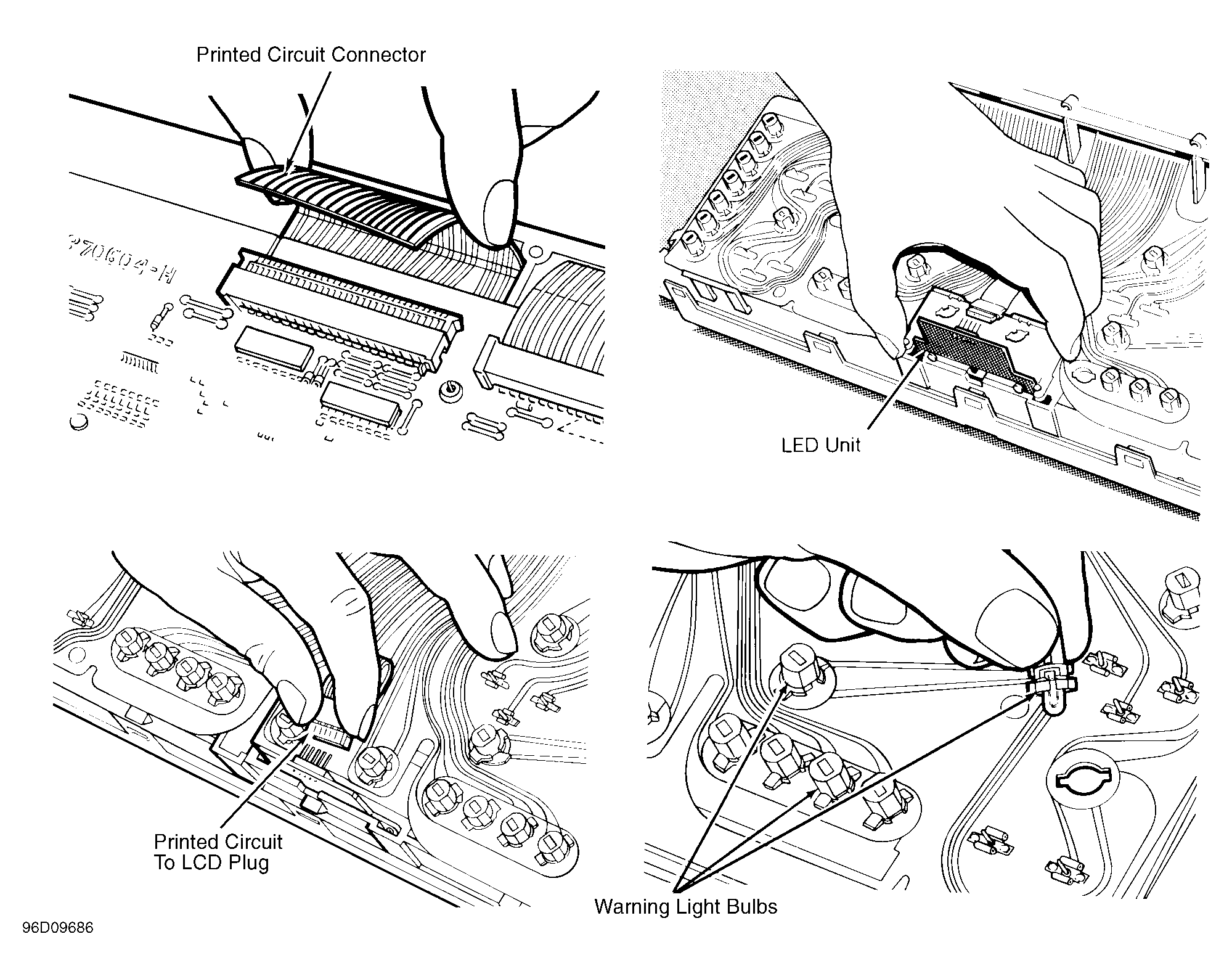 Courtesy of JAGUAR CARS, INC.
- Remove veneer panel securing screws. Release cowl/lens securing clips and remove cowl/lens assembly.
CAUTION:
With cowl/lens removed, DO NOT rest pack face down. Gauge needles are extremely delicate and easily damaged. Take special care not to scratch or damage gauge faces. Ensure cleanliness when handling pack. See Fig 2
.
- Remove veneer panel VERY carefully. Gradually remove oil/water temperature, battery/fuel and speedometer/tachometer gauge sets, easing pins out of printed circuit crimps about .079" (2 mm) at a time.See Fig 2
. Disconnect and remove printed circuit.
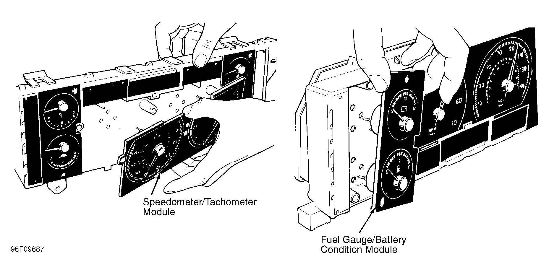 Courtesy of JAGUAR CARS, INC.