Disassembly, Inspection and Assembly
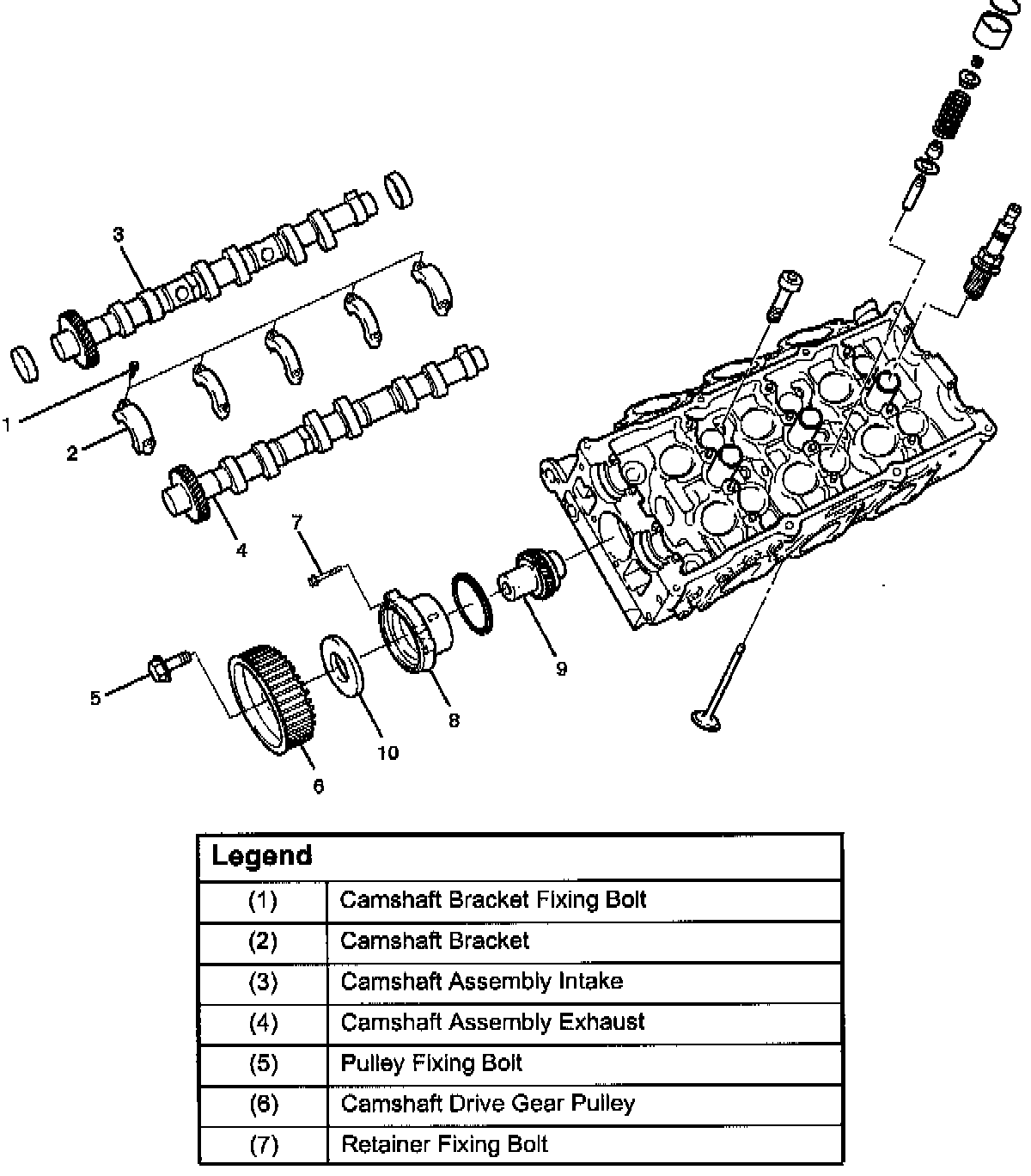
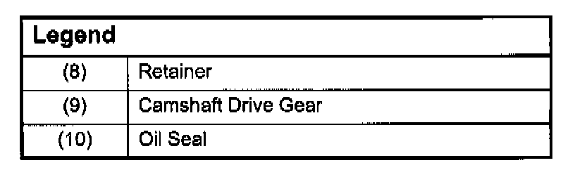
Camshaft
Disassembly
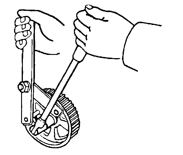
1. Remove fixing bolt (5) for camshaft drive gear pulley using J-43041 universal holder.
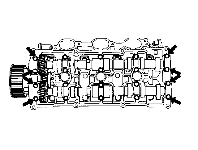
2. Remove twenty fixing bolts from inlet and exhaust camshaft bracket on one side bank, then camshaft brackets (2).
3. Remove camshaft assembly (3), (4).
4. Remove three fixing bolts (7) from camshaft drive gear retainer (8), then camshaft drive gear assembly.
Inspection and Repair
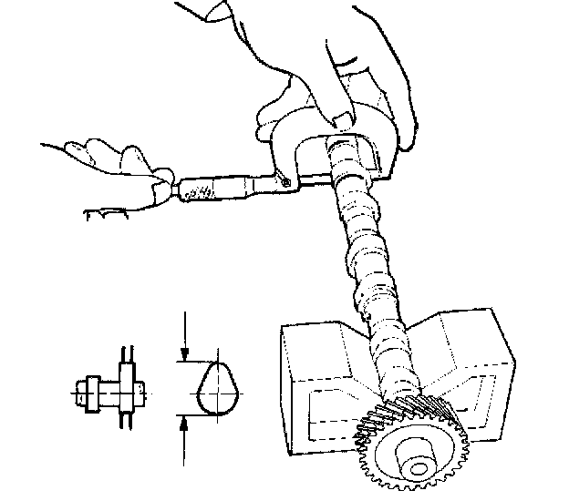
1. Use a micrometer to measure the cam lobe height and uneven wear. Replace the camshaft if either the lobe height or the uneven wear exceeds the specified limit.
Lobe height: 44.709 mm (1.7602 inch)
Uneven wear: 0.05 mm (0.0020 inch)
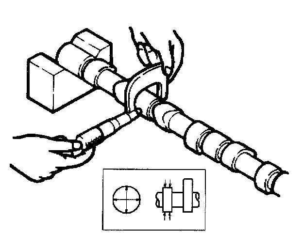
2. Use a micrometer to measure the diameter and the uneven wear of the camshaft journals.
Replace the camshaft if the diameter or the uneven wear exceeds the specified limit.
Journal Diameter
Standard: 25.972 mm - 25.993 mm (1.0225 inch - 1.0233 inch)
Limit: 25.8 mm (1.0157 inch)
Uneven wear: 0.05 mm (0.0020 inch)
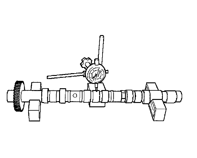
3. Place the camshaft on V-blocks.
Slowly rotate the camshaft and measure the runout with a dial indicator.
Replace the camshaft if the runout exceeds the specified limit.
Run out
Limit: 0.1 mm (0.0039 inch)
4. Measure the camshaft journal oil clearance.
1. Measure the camshaft bracket housing inside diameter.
Note: Tighten camshaft bracket (2) to specified torque before measuring the camshaft bracket inside diameter.
Torque: 10 Nm (89 inch lbs.)
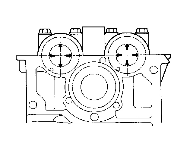
2. Subtract the camshaft outside diameter from the camshaft bracket housing inside diameter.
Oil Clearance
Standard: 0.027 mm - 0.078 mm (0.0011 inch - 0.0031 inch)
Limit: 0.11 mm (0.0043 inch)
5. Replace the cylinder head and/or camshaft if the measured oil clearance exceeds the specified limit.
1. Carefully clean the camshaft journal, the camshaft bracket, and the cylinder head.
2. Install camshaft assembly and camshaft brackets (2), tighten twenty bolts (1) on one side bank to the specified torque.
Torque: 10 Nm (89 inch lbs.)
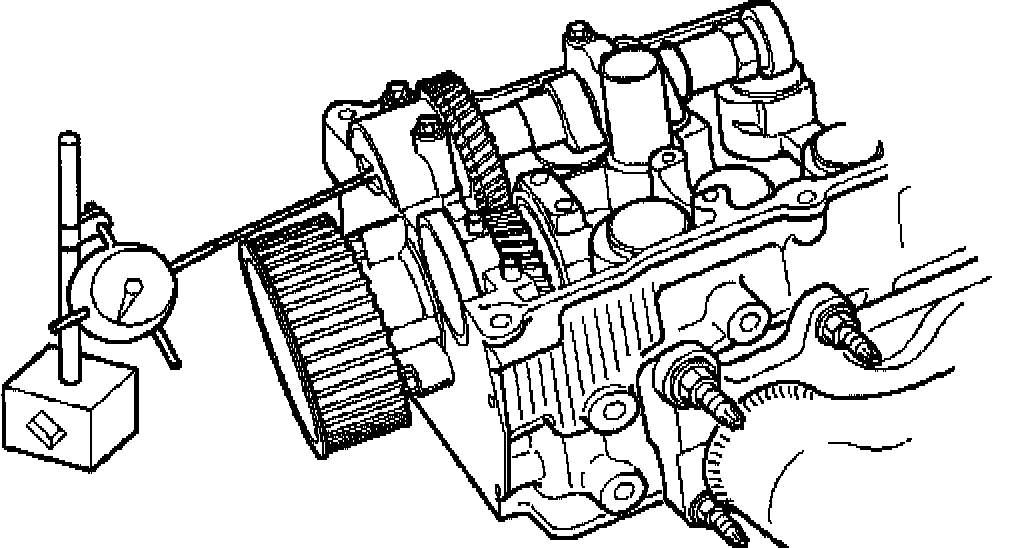
3. Measure the camshaft thrust clearance with a dial indicator. Replace the camshaft and/or the cylinder head if the camshaft thrust clearance exceeds the specified limit.
Camshaft thrust Clearance
Standard: 0.03 mm - 0.08 mm (0.0012 inch - 0.0031 inch)
Limit: 0.12 mm (0.0047 mm)
Reassembly
1. Install camshaft drive gear assembly and tighten three bolts to specified torque.
Torque: 10 Nm (89 inch lbs.)
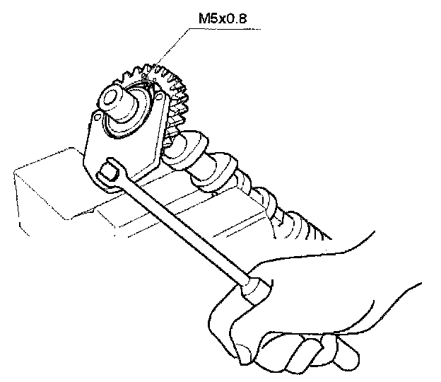
2. Tighten sub gear setting bolt.
1. Use J-42686 to turn sub gear to right direction until the M5 bolt hole aligns between camshaft driven gear and sub gear.
2. Tighten M5 bolt suitable torque for prevent moving the sub gear.
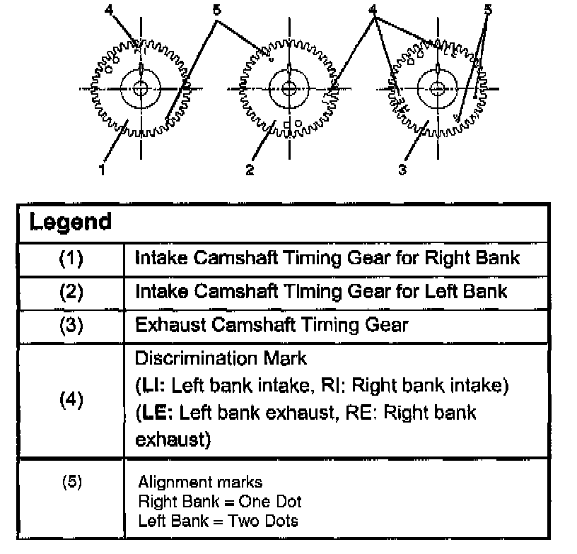
Refer to TSB 1B00-S005 Feb. 2000
3. Install camshaft assembly and camshaft brackets, tighten twenty bolts on one side bank to the specified torque.
1. Apply engine oil to camshaft journal and bearing surface of camshaft bracket.
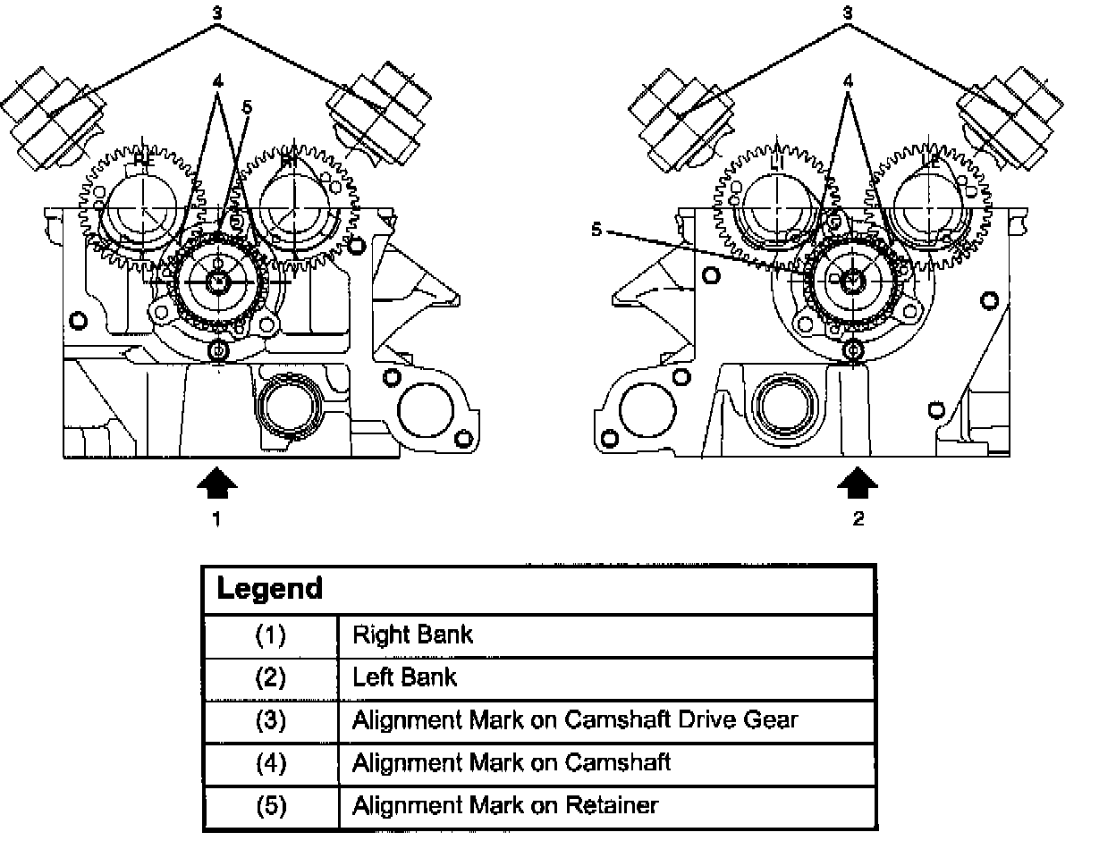
2. Align timing mark on intake camshaft (one dot for right bank, two dots for left bank) and exhaust camshaft (one dot for right bank, two dots for left bank) to timing mark on camshaft drive gear (one dot).
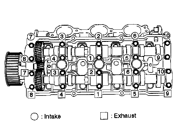
3. Tighten twenty bolts in numerical order on one side bank as shown in the illustration.
Torque: 10 Nm (89 inch lbs.)
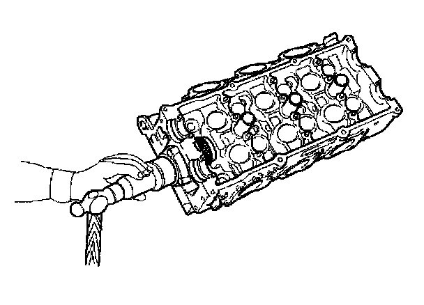
4. If the oil seal requires replacement, use the J-42985 to install the oil seal.
5. Tighten bolt for camshaft drive gear assembly pulley to the specified torque using the J-43041 universal holder.
Torque: 98 Nm (72 ft. lbs.)