Manual Locking Hub: Installation
- Sparingly apply grease to both sides of spacer and inside of ring. Apply grease to splined area of hub body. Assemble inner assembly, spacer, ring and snap ring in body.
- Assemble knob into cover while aligning detent ball and spring. Install snap ring to retain knob. Assemble retaining spring in clutch so that end of spring contacts stop in groove. See Fig 1
.
- Install follower on clutch assembly. Ensure follower tab is positioned close to retaining spring bent end. Hook bent end of spring over follower tab. See Fig 2
.
- Install compression spring with tighter windings against follower. Align follower tab with knob groove. Install clutch assembly on knob while compressing spring and rotating knob counterclockwise.
- Install body assembly to hub/rotor. Tighten bolts to 104 INCH lbs. (11.8 N.m). Install shims and snap ring on end of drive axle. Install shim and snap ring. Using feeler gauge, measure clearance between snap ring and shim. Clearance should be 0-.01" (0-.3 mm). Adjust clearance to specification using different shims (if necessary).
- Apply sealant (Loctite 515) on body-to-cover contact area. Align follower tabs with grooves of body. Install cover and hub bolts. Tighten hub bolts to 43 ft. lbs. (58 N.m). Install brake caliper and wheel. Tighten caliper bolts and wheel lug nuts to specification. See TORQUE SPECIFICATIONS.
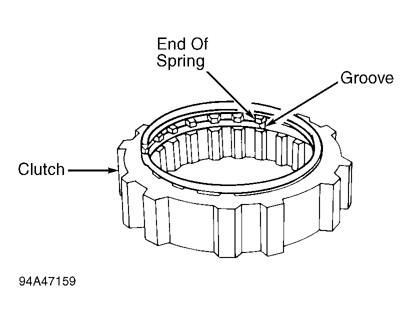 Courtesy of ISUZU MOTOR CO.
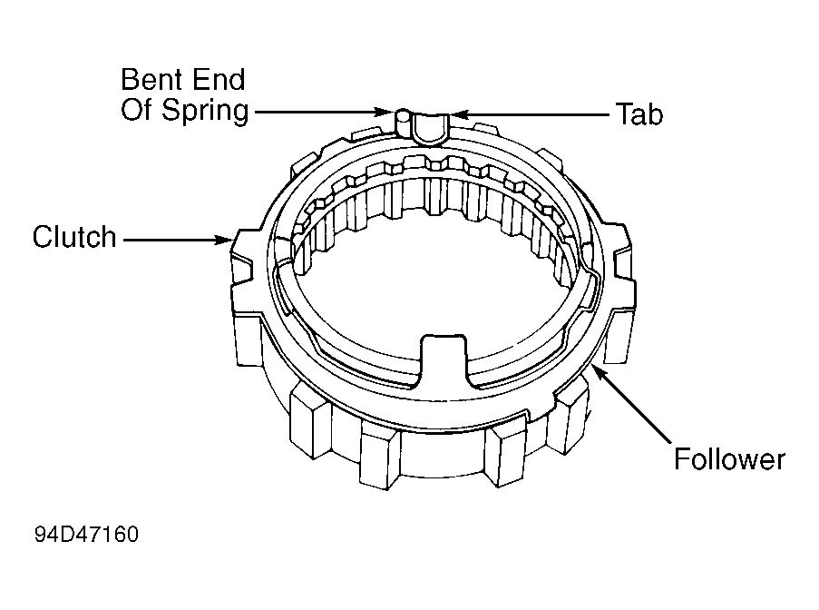 Courtesy of ISUZU MOTOR CO.