- Install thrust washers, side gears and pinion gears into differential cage. Install pinion shaft without lock pin.
- Using dial indicator, measure backlash between pinion and side gear. If backlash is not as specified in SIDE GEAR & PINION BACKLASH SPECIFICATIONS table, adjust by selecting side gear thrust washers of different thickness.
- For 194-mm ring gear, thrust washers are available in thicknesses of .039", .041" and .043" (1.00, 1.05 and 1.10 mm). For 220-mm ring gear, thrust washers are available in increments of .004" (.1 mm) in thicknesses of .031-.051" (.08-1.30 mm). Ensure both sides are equally shimmed. Once backlash is correct, install pinion shaft lock pin.
SIDE GEAR & PINION BACKLASH SPECIFICATIONS
| Application |
In. (mm) |
| 194-mm Ring Gear |
.001-.003 (.03-.08) |
| 220-mm Ring Gear |
.005-.007 (.13-.18) |
- Stake lock pin hole to prevent movement. Install ring gear onto differential cage. Ensure alignment marks on differential cage and ring gear are aligned.
- Apply Loctite to NEW ring gear bolts, and install bolts. Tighten bolts to specification in a diagonal pattern. See TORQUE SPECIFICATIONS. Install side bearings cage. DO NOT install shims. Support opposite end of differential cage to prevent bearing damage.
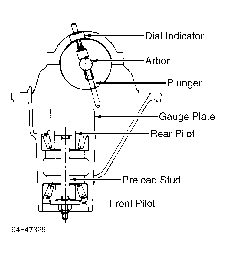
- Install pinion bearing races and pinion bearings. Install Front Pilot (J-21777-42), Preload Stud (J-21777-43), Rear Pilot (J-23597-12) and Gauge Plate (J-23597-42). See Fig 1
. Rotate bearings to ensure they are seated properly. Tighten preload stud nut to 10 INCH lbs. (1.1 N.m) for used bearings, or 20 INCH lbs. (2.3 N.m) for new bearings.
- Clean side bearing bores. Install Mounting Discs (J-21777-86) and Arbor (J23597-1) into side bearing bores. Tighten bearing caps as specified in SIDE BEARING CAP BOLT TORQUE table. Set dial indicator to zero. Install dial indicator onto arbor post. Position plunger on top surface of gauge plate.
 Courtesy of ISUZU MOTOR CO.
 SIDE BEARING CAP BOLT TORQUE
| Application |
Ft. Lbs. (N.m) |
| Amigo & Pickup |
| 194-mm Ring Gear |
65-80 (88-108) |
| 220-mm Ring Gear |
72-87 (98-118) |
| Trooper |
80 (108) |
- Move dial indicator downward on arbor stud until needle rotates one half turn clockwise. Tighten dial indicator at that position. Rotate arbor back and forth until dial indicator indicates maximum deflection. Set dial indicator to zero.
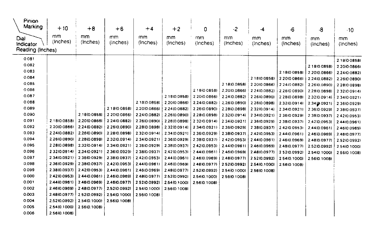
- Repeat procedure to ensure proper setting. Rotate arbor until dial indicator plunger does not contact gauge plate. Record dial indicator reading. This reading is nominal pinion shim thickness.
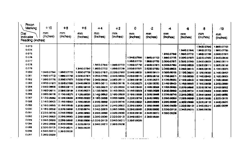
- Note number marked on gear end of drive pinion. Mark may be a zero, a plus (+) or minus (-) number. If mark is zero, pinion is nominal. Combine dial indicator reading and pinion marking to determine proper drive pinion shim thickness. See Fig 2
or Fig 3
.
 Courtesy of ISUZU MOTOR CO.
 Courtesy of ISUZU MOTOR CO.
- Remove bearing caps and pinion depth gauging set. Install selected shim pack, with chamfered side toward gear side of pinion. Press rear pinion bearing onto drive pinion. Lubricate bearing.
- Install drive pinion and NEW collapsible spacer into carrier. Install front pinion bearing. Soak NEW pinion seal in axle lubricant. Install pinion oil seal.
- Install flange onto drive pinion. Lubricate pinion threads. Install NEW pinion nut and washer. Tighten pinion nut as specified in PINION FLANGE NUT TORQUE table. Rotate pinion to ensure bearings are seated.
PINION FLANGE NUT TORQUE
| Application |
Ft. Lb. (N.m) |
| Amigo & Pickup |
| 194-mm Ring Gear |
| New Bearing |
130-203 (176-275) |
| Used Bearing |
65-101 (88-137) |
| 220-mm Ring Gear |
| New Bearing |
181-217 (245-294) |
| Used Bearing |
91-108 (123-147) |
| Trooper |
| New Bearing |
181-217 (245-294) |
| Used Bearing |
91-108 (123-147) |
- Using INCH lb. torque wrench, measure drive pinion preload. If preload is not as specified in PINION PRELOAD TORQUE table, tighten pinion nut until preload is within specification. DO NOT exceed maximum torque specification.
NOTE:
DO NOT loosen flange nut to decrease preload. If preload is exceeded, install a NEW collapsible spacer. Retighten nut until proper preload is attained.
PINION PRELOAD TORQUE
| Application |
INCH Lbs. (N.m) |
| Amigo & Pickup |
| 194-mm Ring Gear |
| New Bearing |
5.3-10 (.6-1.1) |
| Used Bearing |
3-5 (.3-.5) |
| 220-mm Ring Gear |
| New Bearing |
6.1-12 (.7-1.3) |
| Used Bearing |
3-5.6 (.4-.6) |
| Trooper |
| New Bearing |
6.1-12 (.7-1.3) |
| Used Bearing |
3.0-5.6 (.4-.6) |
- Temporarily install side bearings without shims. Install differential assembly and side bearing races into axle housing. Insert feeler gauge of sufficient thickness between each bearing outer race and axle housing to remove all end play. See fig. 8. Ensure each feeler gauge extends to bottom of bearing bores. Lock drive pinion in place.
- Measure ring gear backlash. If backlash is not .005-.007" (.13-.18 mm) for 194-mm axles or .006-.008" (.15-.20 mm) for 220-mm axles, try different feeler gauge thickness on each side to adjust backlash. With zero end play and correct backlash, remove feeler gauges.
- Add .002" (.05 mm) to each feeler gauge thickness to determine required thicknesses of shim packs. Always use NEW shims. Remove differential assembly. Remove side bearings. Install shim packs. Install side bearings onto differential assembly.
- Install differential assembly and outer bearing races into axle housing. Install bearing caps in original locations. Tighten bearing cap bolts to specification. See TORQUE SPECIFICATIONS.
- Measure ring gear runout. If ring gear runout exceeds .002" (.05 mm), correct by cleaning or replacing parts. Check gear tooth contact. See GEAR TOOTH CONTACT PATTERNS article in the GENERAL INFORMATION Section.