1.6L DOHC
- Disconnect negative battery cable. Remove PCV hoses from valve cover. Remove center cover from valve cover. Remove spark plug wires from spark plugs and clips. Remove upper timing belt cover. Remove valve cover bolts, valve cover and gasket.
- Rotate crankshaft so No. 1 cylinder is at TDC of compression stroke. Ensure timing mark on crankshaft pulley aligns with "0" mark on timing belt cover.
- Ensure valves on No. 1 cylinder are free. If valves are tight, rotate crankshaft 360 degrees. Using feeler gauge, check clearance between camshaft lobe and adjuster shim for all valves on No. 1 cylinder, intake valves on No. 2 cylinder and exhaust valves on No. 3 cylinder. Record all readings.
- Rotate crankshaft 360 degrees. Check clearance for all valves on No. 4 cylinder, intake valves on No. 3 cylinder and exhaust valves on No. 2 cylinder. Replace adjuster shim if clearance is not within specification. See VALVE CLEARANCE SPECIFICATIONS
table.
- To adjust valve clearance, replace selective adjuster shim. Rotate cut-away of valve lifter to position where adjuster shim can be removed. See Fig 1
.
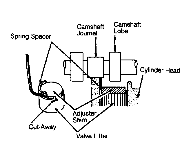 Courtesy of ISUZU MOTOR CO.
- Rotate camshaft lobe downward on valve to be adjusted. Insert Spring Spacer (J-38413-2 or J-38413-3) between camshaft journal and camshaft lobe, next to adjuster shim. See Fig 1
. Rotate camshaft lobe upward. Remove adjuster shim from lifter, using screwdriver and magnet.
- Measure thickness of original adjuster shim. Determine correct thickness of adjusting shim to be used by subtracting appropriate valve clearance specification (See VALVE CLEARANCE SPECIFICATION
table) from measured valve clearance. Add this number to thickness of old shim. Select a new shim with a thickness as close as possible to the calculated value. See appropriate SHIM THICKNESS TABLE. Replace original adjuster shim with correct adjuster shim to obtain correct clearance. See VALVE CLEARANCE SPECIFICATIONS table. Repeat procedure as necessary.
- Before installing valve cover, apply Sealant (TB-1207B) at valve cover-to-camshaft bearing cap surfaces of No. 1 and No. 5 bearing caps. To install valve cover, reverse removal procedure.
- Tighten valve cover bolts in proper sequence. See Figure
. Tighten bolts to specification. See TORQUE SPECIFICATIONS
.