Power Supply & Ground Circuit Check
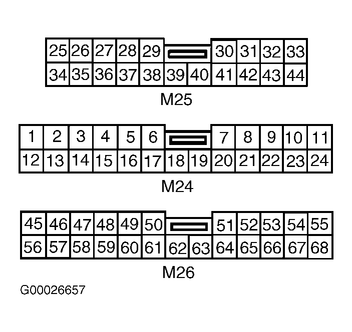
- Disconnect instrument cluster harness connectors. Using a DVOM connected to ground, measure voltage at appropriate instrument cluster connector terminal, with ignition switch in specified positions. See POWER SUPPLY & GROUND CIRCUIT CHECK
. See Fig 1
. If readings are as specified, go to step 3
. If readings are not as specified, go to next step.
- Check fuses No. 12 (10-amp) and No. 30 (10-amp) at instrument panel fuse block. If fuses are open, check for a shorted wiring harness between the instrument cluster and instrument panel fuse block. See WIRING DIAGRAMS
. Replace fuses as necessary. If fuses are okay, go to next step.
- Check for continuity to ground at instrument cluster harness connector M26, terminal No. 59 (Black wire). See Fig 1
. If continuity exists, power and ground circuit check is complete. If continuity does not exist, check for an open in power supply circuit between the instrument cluster and instrument panel fuse block fuses No. 12 (10-amp) and No. 30 (10-amp). See WIRING DIAGRAMS
.
POWER SUPPLY & GROUND CIRCUIT CHECK
| Between Terminal & Ground |
Ignition Switch Position |
DVOM Reading |
| No. 31 (Green/Red Wire) |
OFF |
Zero Volts |
| ..... |
ACC |
Battery Voltage |
| ..... |
ON |
Battery Voltage |
| No. 62 (Green/Red Wire) |
OFF |
Battery Voltage |
| ..... |
ACC |
Battery Voltage |
| ..... |
ON |
Battery Voltage |
| No. 66 (White/Black Wire) |
OFF |
Zero Volts |
| ..... |
ACC |
Zero Volts |
| ..... |
ON |
Battery Voltage |
| No. 59 (Black Wire) |
Any |
Continuity |
| No. 63 (Light Blue Wire) |
Any |
Continuity |
 Courtesy of NISSAN MOTOR CO., U.S.A.