Power Supply & Ground Circuit Check
- Disconnect combination meter harness connectors. Using a DVOM connected to ground, measure voltage at appropriate combination meter connector terminal, with ignition switch in specified positions. See POWER SUPPLY CHECK
table. See Fig 1
. If readings are as specified, go to step 3
. If readings are not as specified, go to next step.
- Check 10-amp fuses No. 6, 9 and 21 of instrument panel fuse block located at left end of dash. If fuses are open, check for a shorted wiring harness between the combination meter and instrument panel fuse block. Replace fuses as necessary. If fuses are okay, go to next step.
POWER SUPPLY CHECK
| Between Connector/Terminal & Ground |
Ignition Switch Position |
DVOM Reading |
| M41/No. 1 |
OFF |
Zero Voltage |
| ..... |
ACC |
Battery Voltage |
| ..... |
ON |
Battery Voltage |
| M43/No. 57 |
OFF |
Zero Voltage |
| ..... |
ACC |
Zero Voltage |
| ..... |
ON |
Battery Voltage |
| M43/No 59 |
OFF |
Zero Voltage |
| ..... |
ACC |
Zero Voltage |
| ..... |
ON |
Battery Voltage |
- Check for continuity to ground at combination meter harness connector M43, terminals No. 60, 61 and 62 (Black wire). See Fig 1
. If continuity exists, power and ground check is complete. If continuity does not exist, check for an open ground circuit or poor connection. See WIRING DIAGRAMS
.
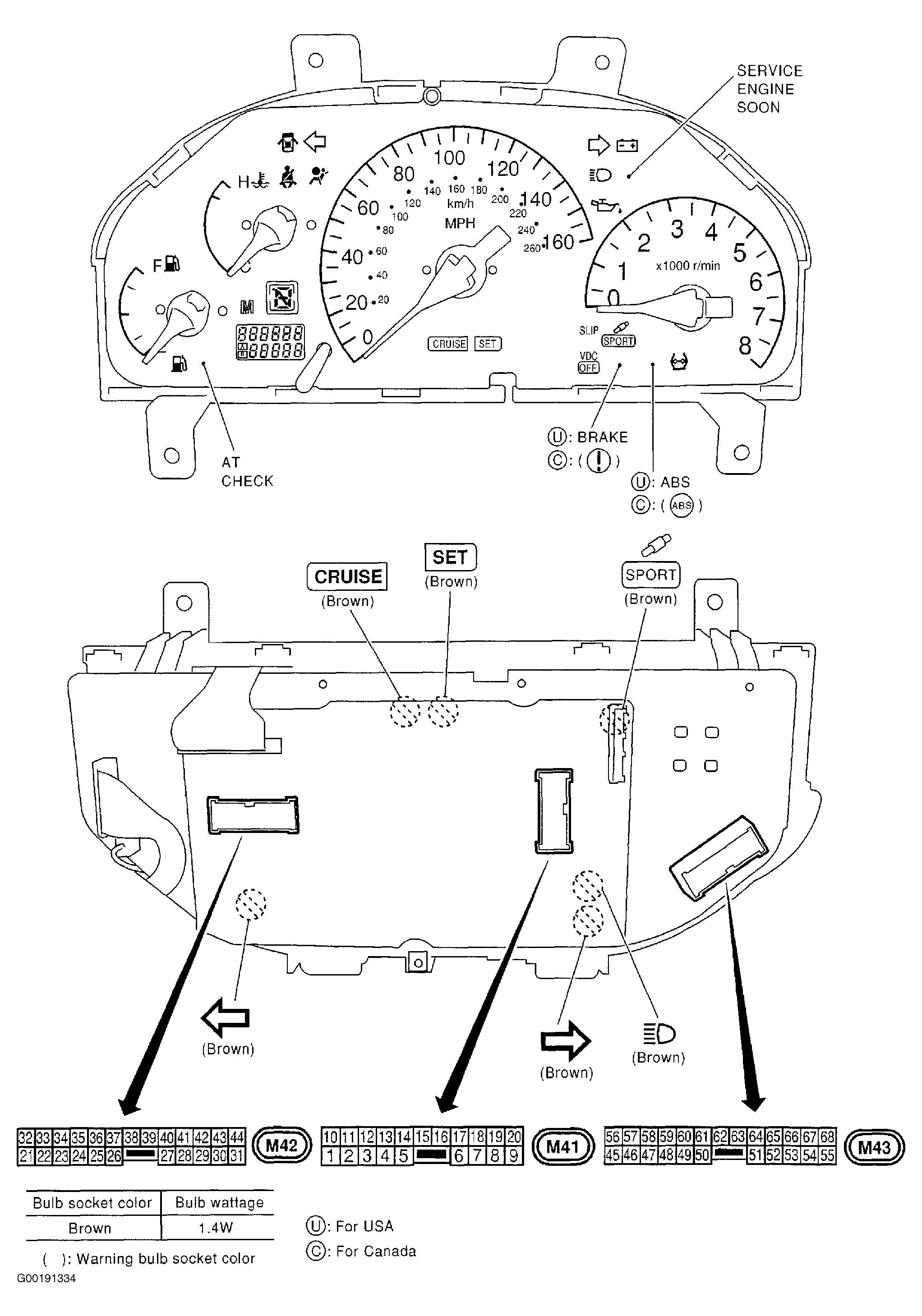 Courtesy of NISSAN MOTOR CO., U.S.A.