Power Supply & Ground Circuit Check
- Disconnect instrument panel White 16-pin harness connector M24. See Figure
. Measure voltage at terminal No. 12 (White/Black wire) at instrument panel harness connector M24. See Fig 1
. If battery voltage exists only with ignition switch in RUN and START positions, go to next step. If battery voltage exists with ignition switch in any other position, repair short to voltage in White/Black wire between combination meter and fuse No. 8 (10-amp) in instrument panel fuse box. If battery voltage does not exist with ignition switch in RUN and START positions, check for the following and repair as necessary:
- Blown fuse No. 8 (10-amp) in instrument panel fuse box.
- Open in White/Black wire between combination meter and fuse No. 8. See WIRING DIAGRAMS
.
- Problem in power distribution circuit. See POWER DISTRIBUTION article in WIRING DIAGRAMS.
- Measure voltage at terminal No. 3 (Green wire) at combination meter harness connector M24. If battery voltage exists with ignition switch in all positions, go to next step. If battery voltage does not exist with ignition switch in all positions, check for the following and repair as necessary:
- Blown fuse No. 24 (7.5-amp) in instrument panel fuse box.
- Open in Green wire between combination meter and fuse No. 24. See WIRING DIAGRAMS
.
- Problem in power distribution circuit. See POWER DISTRIBUTION article in WIRING DIAGRAMS.
- Ensure ignition switch is in OFF position. Measure resistance between ground and terminal No. 2 (Black wire) at combination meter harness connector M24. If resistance is 5 ohms or less, combination meter power and ground circuits are okay at this time. If resistance is greater than 5 ohms, repair open in Black wire between combination meter and ground.
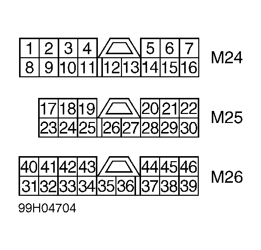 Courtesy of NISSAN MOTOR CO., U.S.A.