Intermittent Front Wiper Does Not Operate: Q45
- If using Nissan's CONSULT scan tool, go to next step. If not using scan tool, go to step 6.
- Turn ignition switch to LOCK position. Connect scan tool to Data Link Connector (DLC). See Fig 1. Turn ignition switch to RUN position. Touch START, IVMS, then WIPER on scan tool display. Touch DATA MONITOR on scan tool display. Select INT SW on scan tool. When wiper switch is in INT position, scan tool should display INT SW ON. When wiper switch is in OFF position, scan tool should display INT SW OFF. If scan tool display is as specified, go to next step. If scan tool display is not as specified, check the following and repair as necessary:
- Test wiper switch. See STEERING COLUMN SWITCHES article.
- Check for open in wiper switch ground circuit. See WIRING DIAGRAMS .
- Check for open and/or shorts between Body Control Module (BCM) and wiper switch. See WIRING DIAGRAMS .
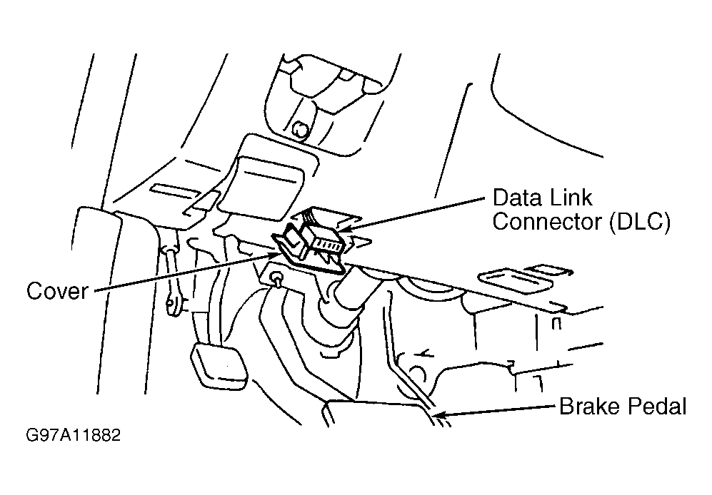 Courtesy of NISSAN MOTOR CO., U.S.A.
- Using scan tool, access WIP AUTO STOP in DATA MONITOR mode. When wiper switch is in INT and OFF positions, scan tool should display WIP AUTO STOP ACC. When wiper switch is in LO or HI positions, scan tool should display WIP AUTO STOP GND. If scan tool display is as specified, go to next step. If scan tool display is not as specified, check the following and repair as necessary:
- Using scan tool, access IGN ACC SW in DATA MONITOR mode. When ignition switch is in ACC and ON positions, scan tool should display IGN ACC SW ON. When ignition switch is in OFF position, scan tool should display IGN ACC SW OFF. If scan tool display is as specified, go to next step. If scan tool display is not as specified, check the following and repair as necessary:
- Check fuse No. 23 (7.5-amp) in instrument panel fuse box.
- Check Orange wire for open and/or short between BCM and instrument panel fuse box. See WIRING DIAGRAMS .
- Using scan tool, access WIPER AMP in ACTIVE TEST mode. Follow procedure on scan tool display. Wiper motor should operate. If wiper motor operates, replace BCM. If wiper motor does not operate, go to WIPER & WASHER ACTIVATE INDIVIDUALLY, BUT INTERMITTENT WIPER & WASHER COMBINATION DOES NOT OPERATE .
- Perform on-board diagnostics using mode II diagnostics. See MODE II (SWITCH SIGNAL MONITOR) under SELF-DIAGNOSTIC SYSTEM in appropriate MULTIPLEX CONTROL SYSTEMS article. If on-board diagnostics indicate intermittent wiper switch is functioning, go to next step. If on-board diagnostics do not indicate intermittent wiper switch is functioning, check the following and repair as necessary:
- Test wiper switch. See STEERING COLUMN SWITCHES article.
- Check for open in wiper switch ground circuit. See WIRING DIAGRAMS .
- Check for open and/or shorts between Body Control Module (BCM) and wiper switch. See WIRING DIAGRAMS .
- Turn ignition switch to ACC position. Turn wiper switch to LO or HI position. Using a voltmeter, backprobe terminal No. 38 (Red wire) at BCM harness connector. See Fig 2. When wipers are moving, zero volts should exist. When wipers are stopped, battery voltage should exist. If voltage is as specified, go to next step. If voltage is not as specified, check the following and repair as necessary:
- Using a voltmeter, backprobe terminal No. 60 (Orange wire) at BCM harness connector. When ignition switch is in ACC or ON position, battery voltage should exist. When ignition switch is in OFF position, zero volts should exist. If voltage is as specified, go to WIPER & WASHER ACTIVATE INDIVIDUALLY, BUT INTERMITTENT WIPER & WASHER COMBINATION DOES NOT OPERATE . If voltage is not as specified, check the following and repair as necessary:
- Check fuse No. 23 (7.5-amp) in instrument panel fuse box.
- Check Orange wire for open and/or short between BCM and instrument panel fuse box. See WIRING DIAGRAMS .
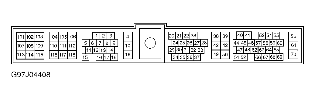 Courtesy of NISSAN MOTOR CO., U.S.A.