Coolant Temperature Gauge Circuit Test
- Turn ignition on. Using a DVOM, measure voltage between ground and terminal No. 23 of instrument cluster connector No. 3. See Fig 1
. If battery voltage is present, go to step 3). If battery voltag e is not present, go to next step.
- Check wiring harness between power source and instrument cluster. See WIRING DIAGRAMS
. Check for blown fuse and/or fusible link. Check ignition switch and ignition relay. Repair as necessary.
- Turn ignition on. Using a fused jumper wire, ground coolant temperature gauge terminal for less than 10 seconds. See Fig 2
. Gauge should move smoothly to full scale ("H") position. Replace gauge if it does not function as described. If gauge functions as described, go to next step.
- Turn ignition off. Using a DVOM, check for continuity between ground and terminal No. 5 of instrument cluster connector No. 1. See Fig 1
. If continuity is not present, repair Black/Red wire for an open or poor connection between instrument cluster and thermal transmitter. If continuity is present, test thermal transmitter. See THERMAL TRANSMITTER
under COMPONENT TESTS.
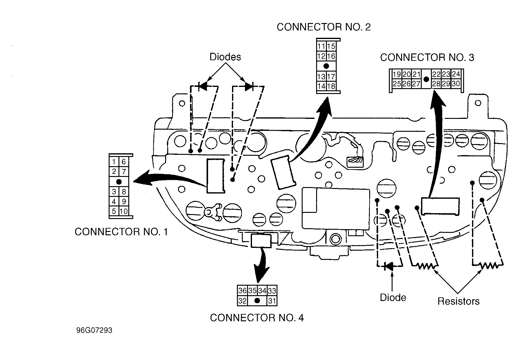 Courtesy of NISSAN MOTOR CO., U.S.A.
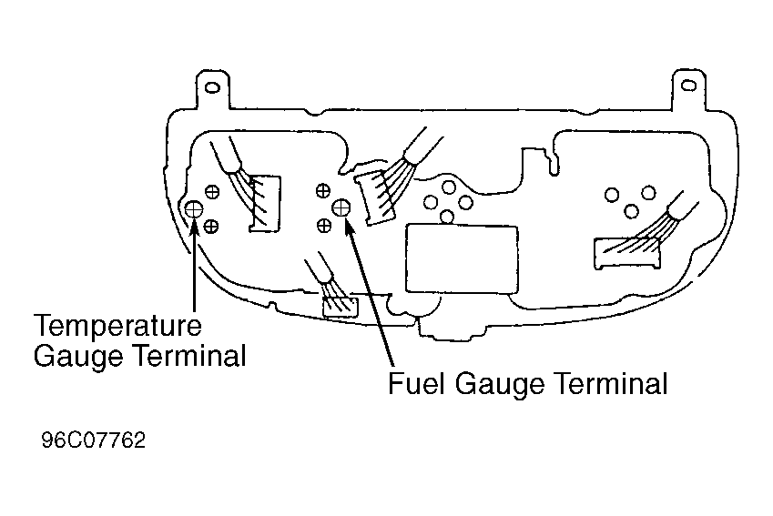 Courtesy of NISSAN MOTOR CO., U.S.A.