- If crankshaft sprocket was removed, install crankshaft sprocket with teeth away from cylinder block. This will position shoulder on rear of crankshaft sprocket toward cylinder block.
- Rotate crankshaft until No. 1 cylinder is at TDC of compression stroke. This will position crankshaft keyway at 12 o'clock and timing mark at 4 o'clock positions. See Figure
.
- Install timing chain so timing mark (gold link) is aligned with timing mark on crankshaft sprocket. See Figure
. Install lower timing chain guides. Tighten retaining bolts to specification. See TORQUE SPECIFICATIONS
.
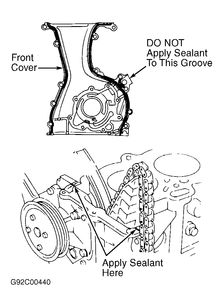
- Install oil pump spacer (if removed). Apply a .08-.12" (2-3 mm) diameter bead of sealant to front cover. DO NOT apply sealant to outer groove on front cover. See Fig 1
. Install front cover. Tighten retaining bolts to specification. See TORQUE SPECIFICATIONS
. Clean sealant from top and bottom of front cover at cylinder block.
 Courtesy of NISSAN MOTOR CO., U.S.A.
- Install front engine mount. Tighten bolts to specification. See TORQUE SPECIFICATIONS
. Coat seal lip of new front cover oil seal with engine oil. Install crankshaft pulley.
- Coat crankshaft pulley retaining bolt threads and seat area below head of bolt with oil. Install and tighten retaining bolt to specification. See TORQUE SPECIFICATIONS
.
- Rotate crankshaft until No. 1 cylinder is at TDC of compression stroke and timing mark pointer on front cover aligns with "0" mark on crankshaft pulley.
- Install new "O" ring, oil pump pick-up tube and baffle plate. Tighten bolts to specification. See TORQUE SPECIFICATIONS
. Install oil pan. See OIL PAN
under REMOVAL & INSTALLATION.
- Apply a .08-.12" (2-3 mm) diameter bead of sealant where front cover contacts cylinder block. See Fig 1
. Install cylinder head gasket and cylinder head.
CAUTION:
Measure distance from bottom of head to end of bolt on all cylinder head-to-cylinder block bolts before installing. Cylinder head bolt must be replaced if distance exceeds 6.228" (158.19 mm).
- Coat all cylinder head bolt threads and seat area below head of bolt with oil. Install and tighten cylinder head-to-cylinder block bolts to specification in sequence using cylinder head bolt wrench. See Figure
. See TORQUE SPECIFICATIONS
.
- Install outside cylinder head bolts, located at front cover and near distributor. Install starter and necessary coolant hoses.
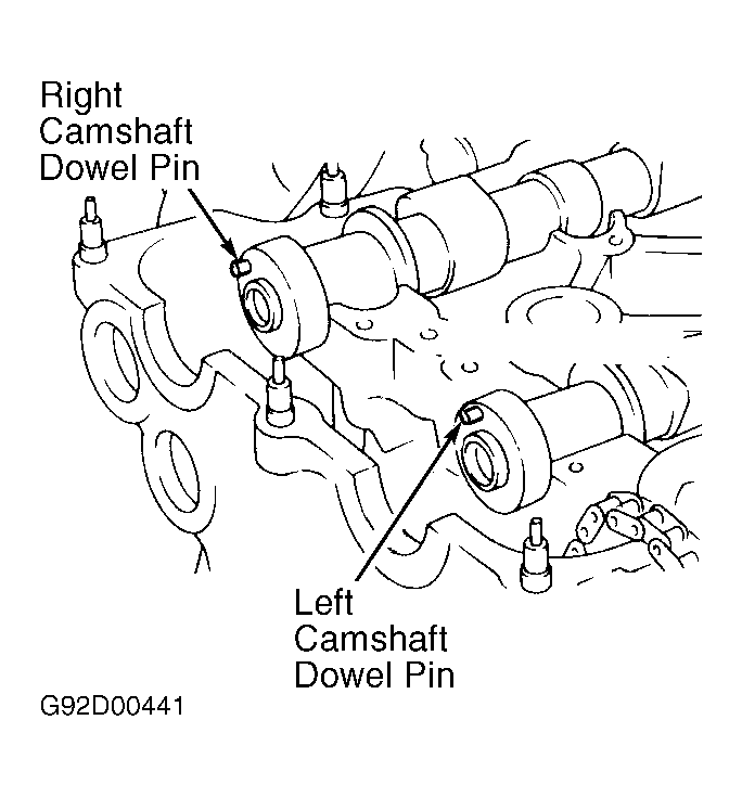
- Coat camshaft and rocker arm components with engine oil. Install camshafts in cylinder head. Dowel pin should be at 12 o'clock position on left camshaft and 10 o'clock position on right camshaft. See Fig 2
.
 Courtesy of NISSAN MOTOR CO., U.S.A.
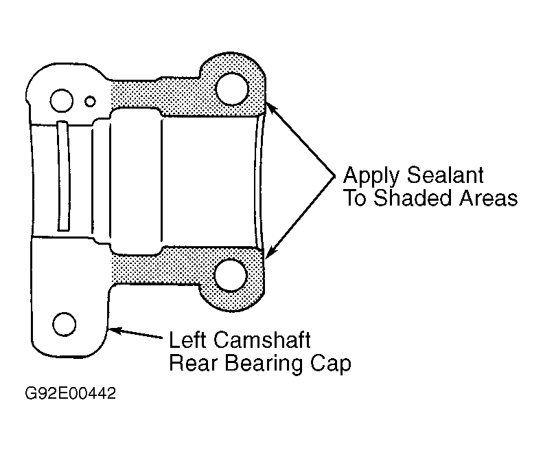
- Apply sealant to designated area on left camshaft rear camshaft bearing cap. See Fig 3
. Install all camshaft bearing caps in original locations.
CAUTION:
Ensure camshaft bearing caps are installed with arrow pointing toward timing chain side of engine. No. 1-4 bearing caps are numbered for location with No. 1 at timing chain side. Rear (end) camshaft bearing caps are not numbered.
 Courtesy of NISSAN MOTOR CO., U.S.A.
- Coat camshaft bearing cap bolt threads and seat area below head of bolt with oil. Install and tighten camshaft bearing cap bolts to specification in sequence. See Figure
. See TORQUE SPECIFICATIONS
.
- Ensure camshaft end play is within specification. See CAMSHAFT
table under ENGINE SPECIFICATIONS.
CAUTION:
DO NOT rotate crankshaft or camshafts with timing chain removed or engine damage may result.
- Install timing chain and camshaft sprockets. Ensure timing marks on camshaft sprockets are aligned with timing marks (silver links) on timing chain. See Figure
.
- Coat camshaft sprocket retaining bolt threads and seat area below head of bolt with oil. Install and tighten camshaft sprocket retaining bolts to specification while holding camshaft. See TORQUE SPECIFICATIONS
.
- Install upper timing chain guide. Tighten retaining bolt to specification. See TORQUE SPECIFICATIONS
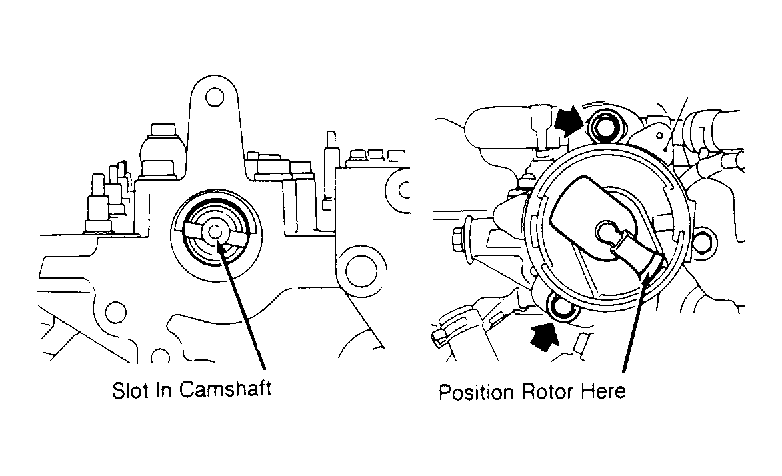
. Ensure slot in camshaft is properly positioned, and install distributor. See Fig 4
.
 Courtesy of NISSAN MOTOR CO., U.S.A.
- Press cam stopper downward on timing chain tensioner and press sleeve inward until hook can be engaged on pin. See Fig 5
. This will hold timing chain tensioner in retracted position for installation.
- Coat timing chain tensioner with engine oil. Install new "O" ring, timing chain tensioner and gasket. Tighten retaining bolt/nut to specification. See TORQUE SPECIFICATIONS
.
CAUTION:
Timing chain tensioner must be installed with arrow pointing toward timing chain side of engine. Arrow is located between bolt holes on outside of timing chain tensioner. See Fig 5
. Timing chain tensioner will release automatically when installed on cylinder head.
- Install oil filter and power steering pump brackets. Tighten bolts to specification. See TORQUE SPECIFICATIONS
. Apply sealant to designated area on valve cover gasket and cylinder head. See Fig 6
. Install gasket, valve cover and oil separator. Tighten valve cover nuts to specification in sequence. See Figure
.
- To install remaining components, reverse removal procedure. Tighten bolts to specification. See TORQUE SPECIFICATIONS
. Adjust fluid levels. Fill and bleed cooling system. See COOLING SYSTEM BLEEDING
under REMOVAL & INSTALLATION.