Diagnostic Procedure Charts (M30)
For component locations and wiring schematics of Anti-Lock Brake System (ABS), see Figure
through Figure
. For ground check, see Fig 1
. For diagnostic procedures No. 1-11, see Fig 2
through Figure
. For electronic components check, see Fig 13
.
NOTE:
For additional wiring diagrams, see Figure
through Figure
at end of article and appropriate chassis wiring diagrams in WIRING DIAGRAMS.
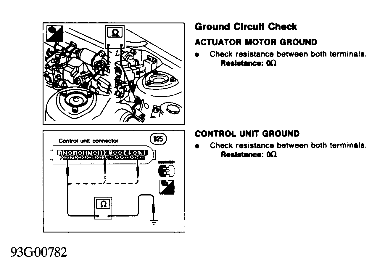 Courtesy of NISSAN MOTOR CO., U.S.A.
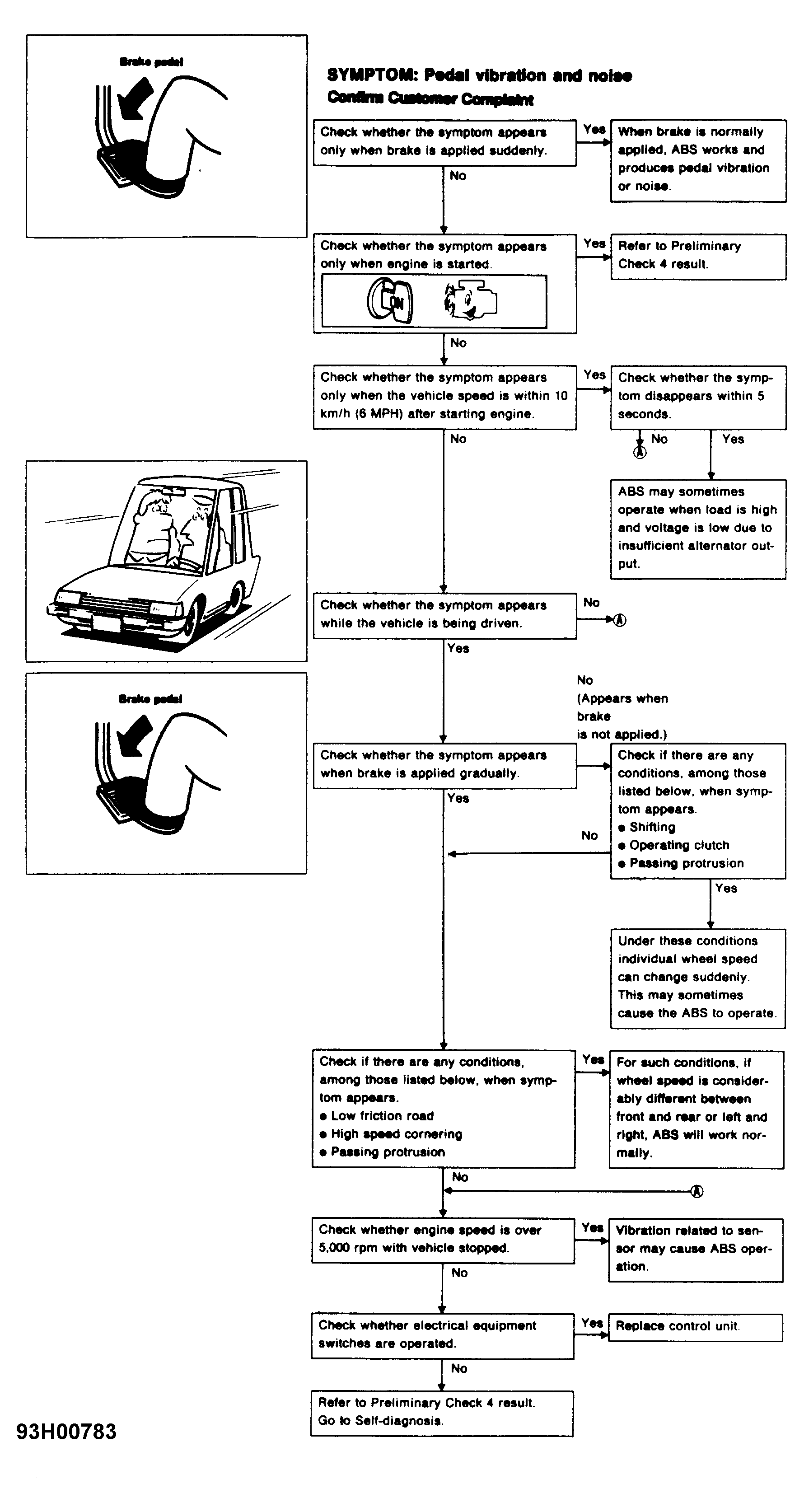 Courtesy of NISSAN MOTOR CO., U.S.A.
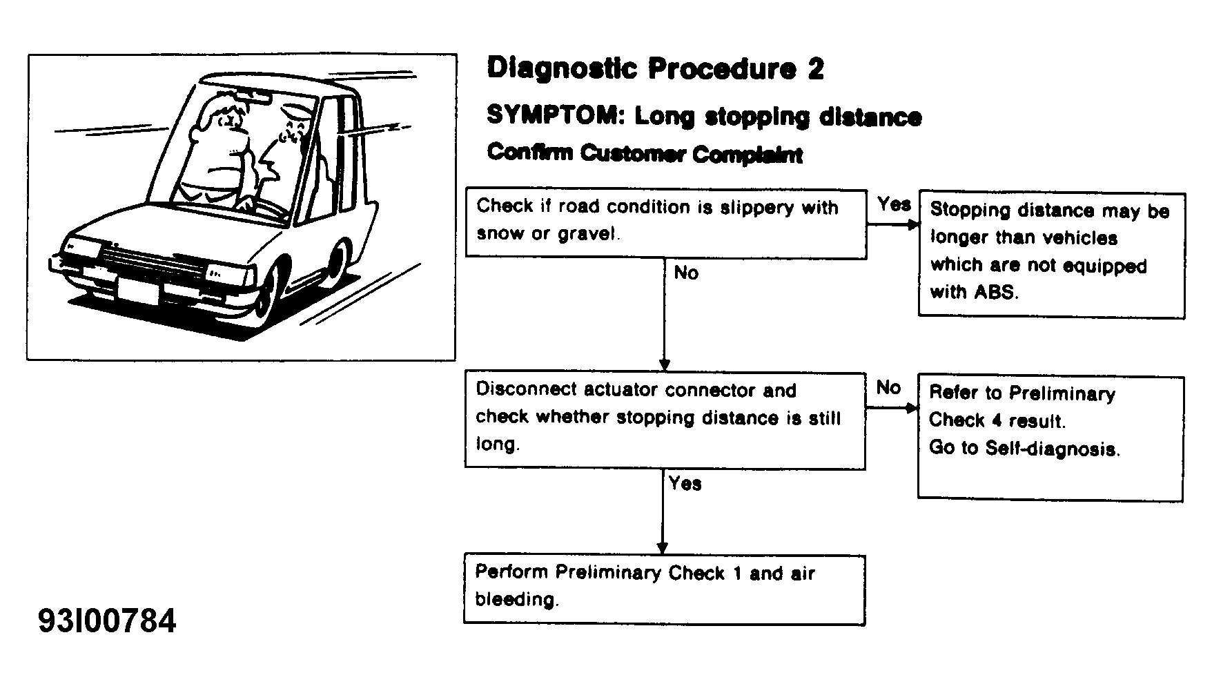 Courtesy of NISSAN MOTOR CO., U.S.A.
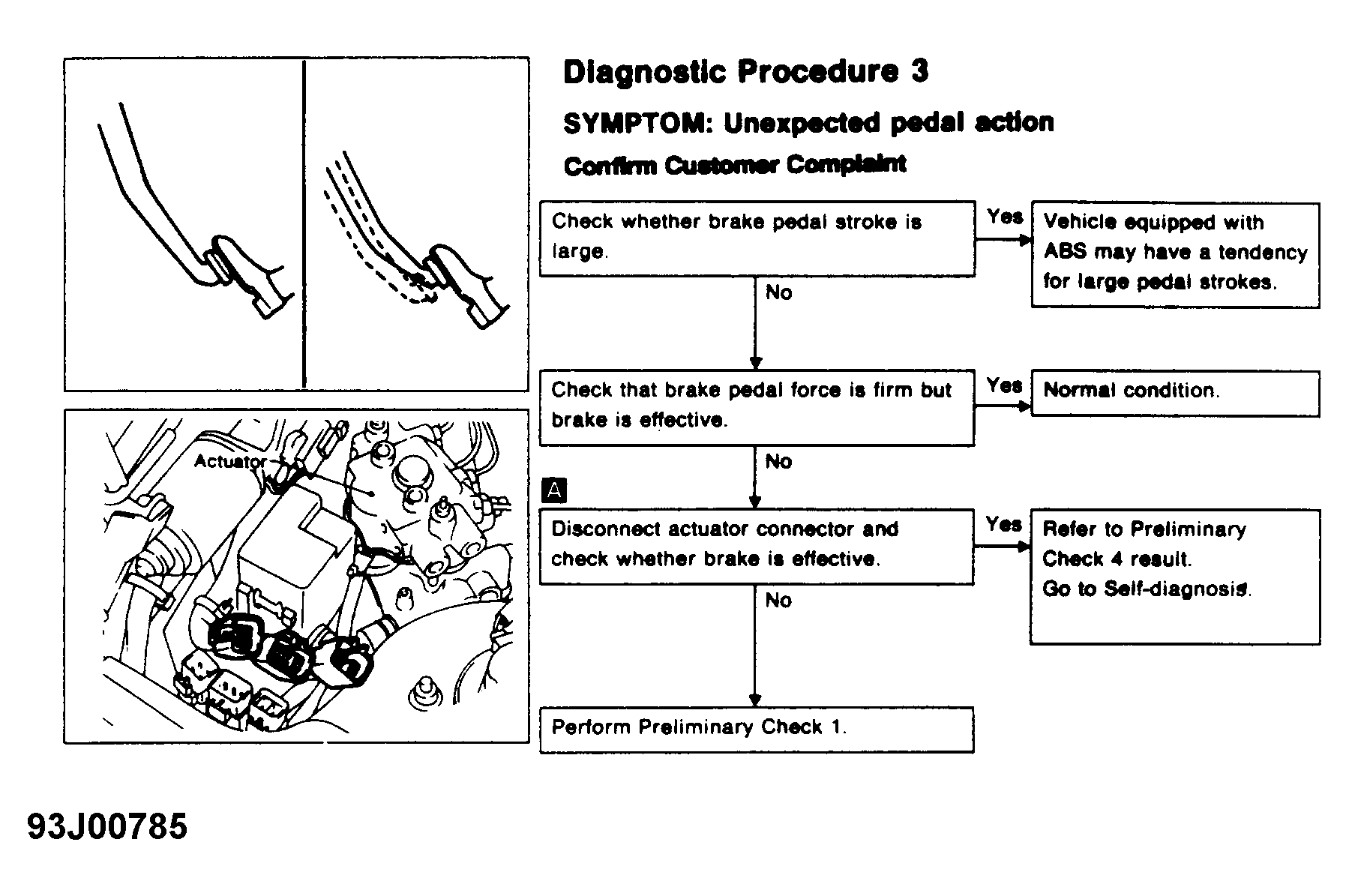 Courtesy of NISSAN MOTOR CO., U.S.A.
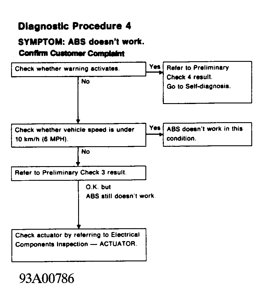 Courtesy of NISSAN MOTOR CO., U.S.A.
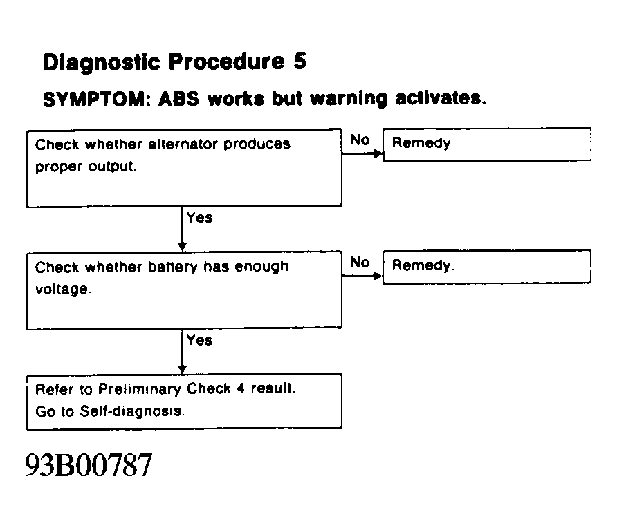 Courtesy of NISSAN MOTOR CO., U.S.A.
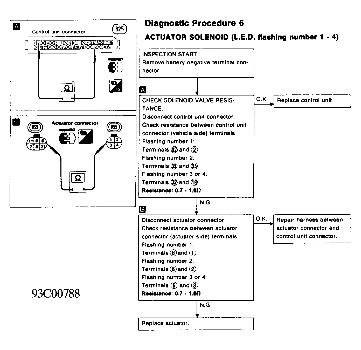 Courtesy of NISSAN MOTOR CO., U.S.A.
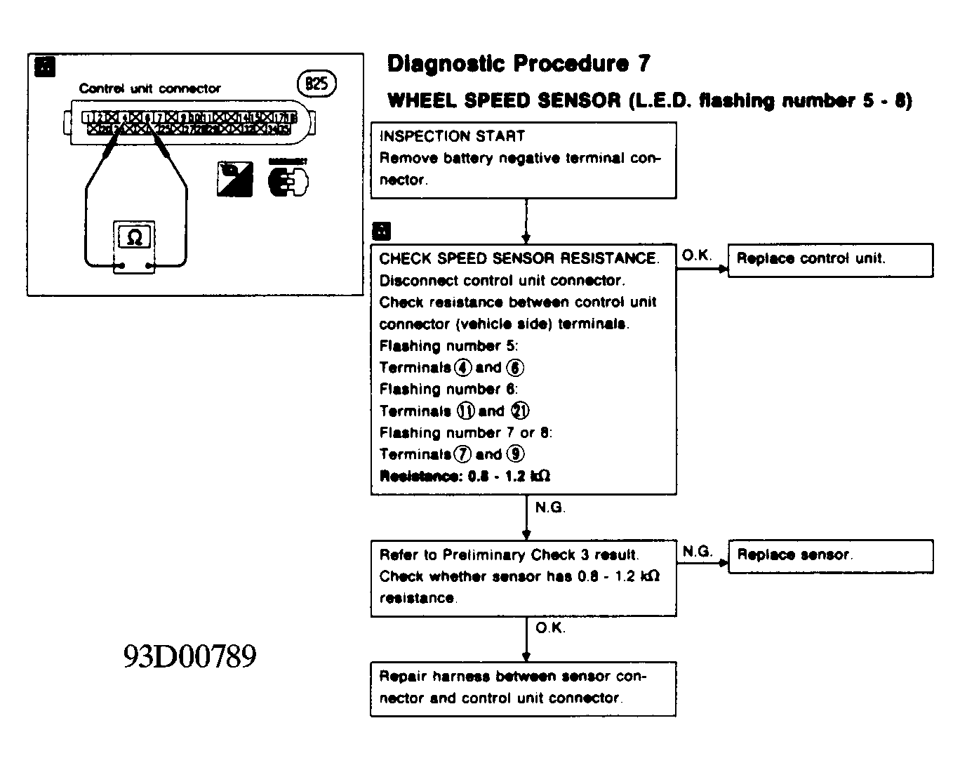 Courtesy of NISSAN MOTOR CO., U.S.A.
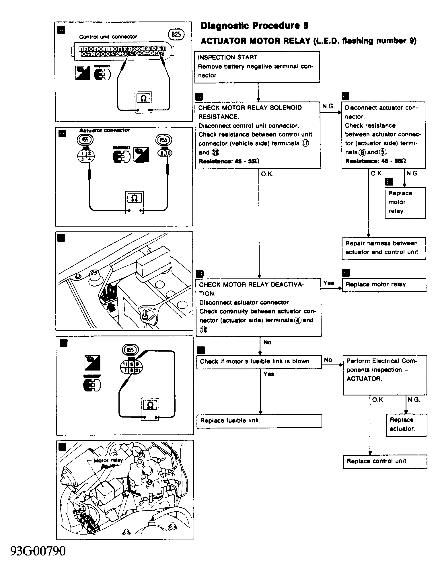 Courtesy of NISSAN MOTOR CO., U.S.A.
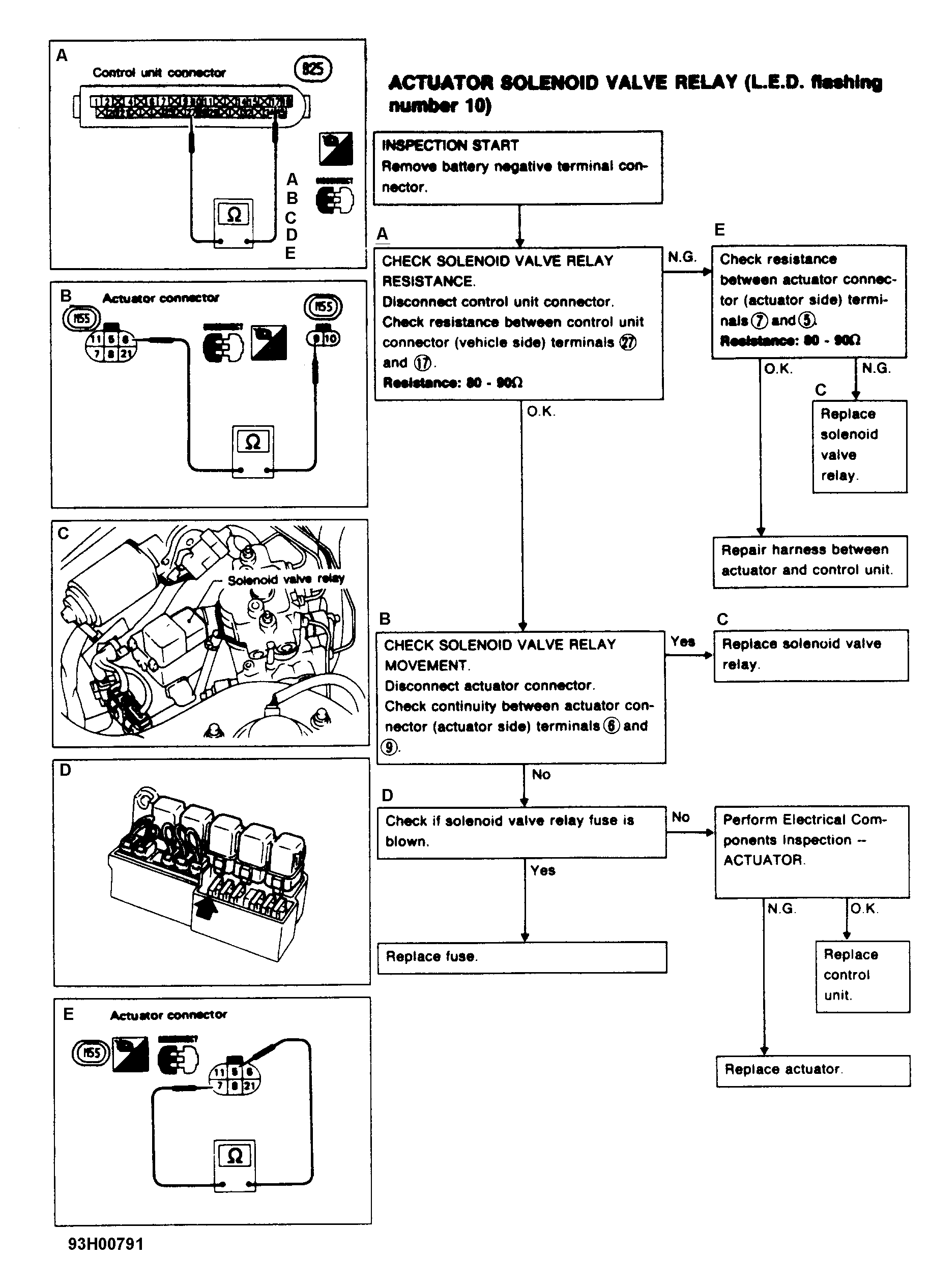 Courtesy of NISSAN MOTOR CO., U.S.A.
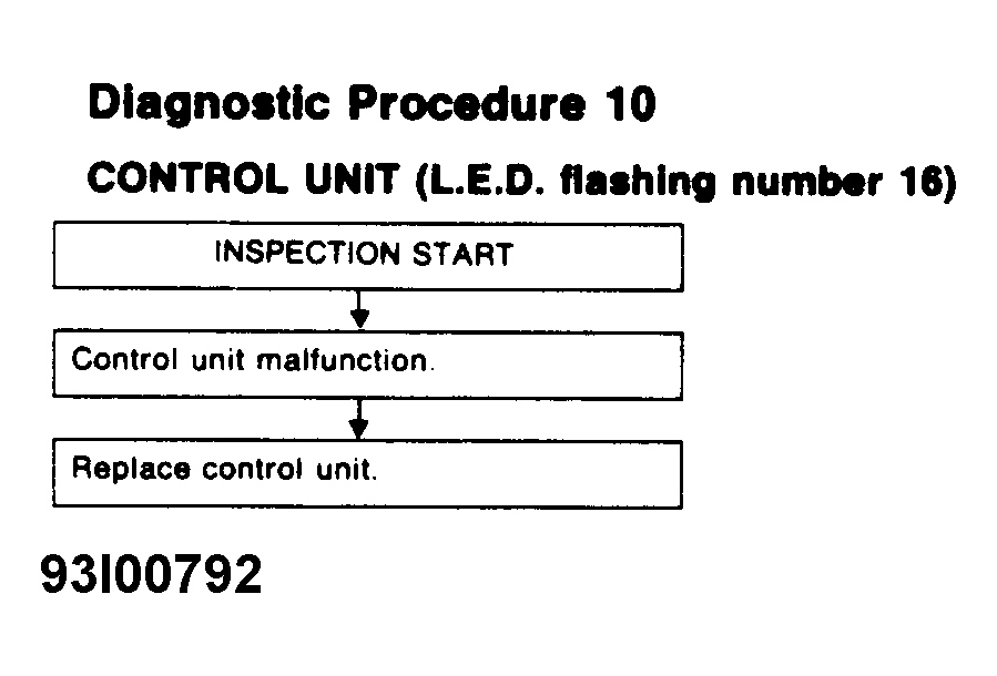 Courtesy of NISSAN MOTOR CO., U.S.A.
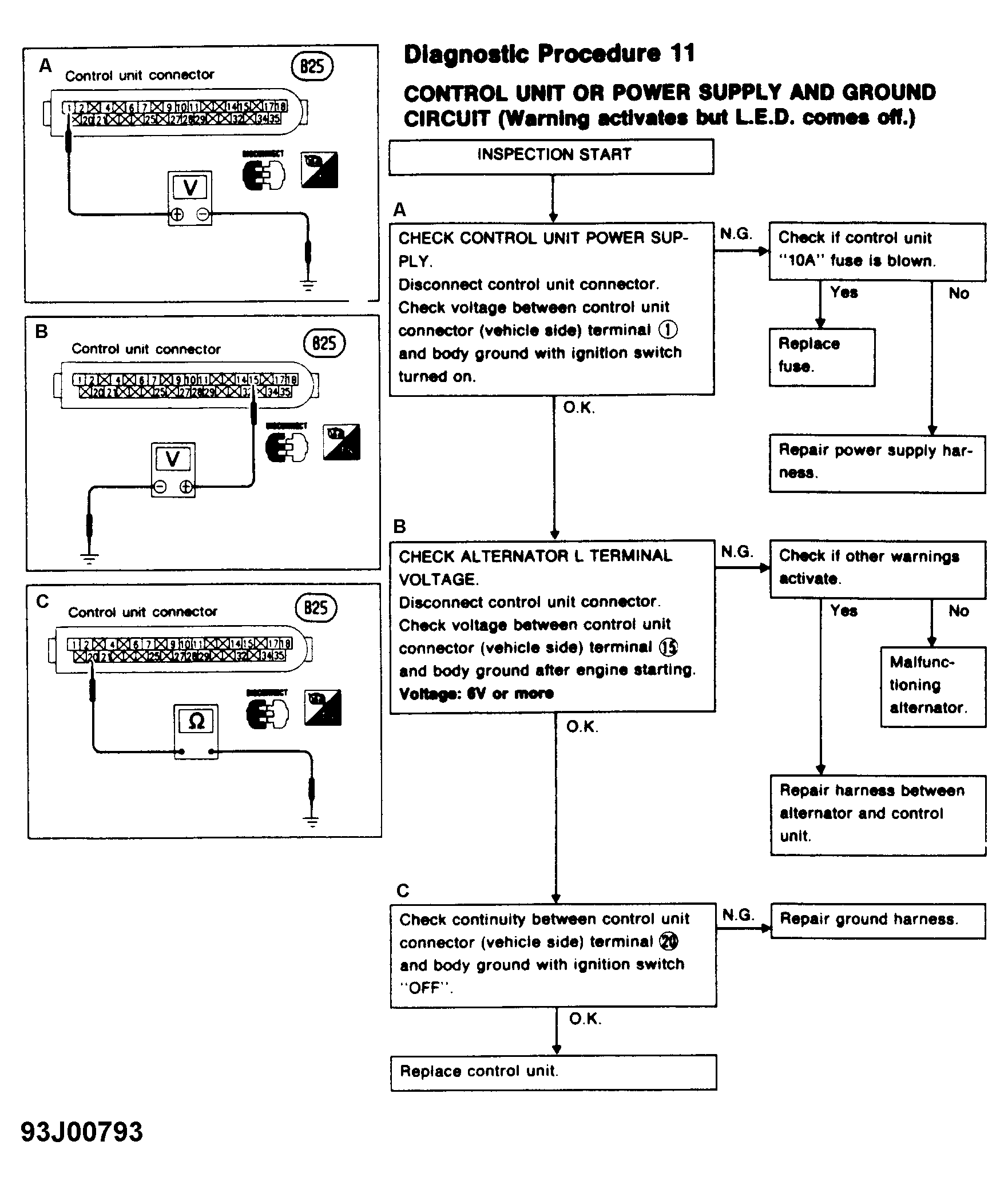 Courtesy of NISSAN MOTOR CO., U.S.A.
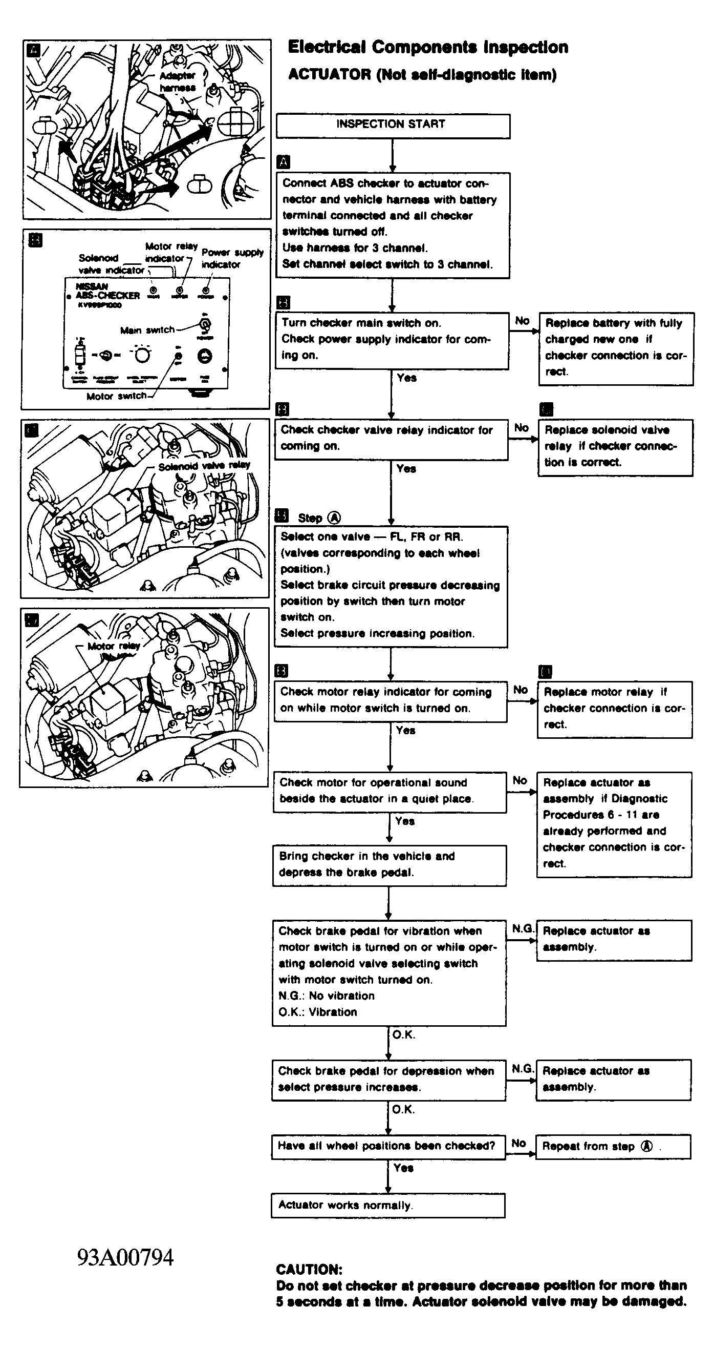 Courtesy of NISSAN MOTOR CO., U.S.A.