Speed Sensor Signal Check: Q45
- To check power source, turn ignition on. Check voltage between terminal No. 1 and ground. See Figure
. If battery voltage is present, go to step 3).
- If battery voltage is not present, check for blown fuse or fusible link. Check continuity between battery terminal and instrument cluster. Check battery circuit from ignition switch and relay. See appropriate chassis wiring diagram in the WIRING DIAGRAMS
Section.
- Check harness connector continuity between terminal No. 5 and ground. If continuity exists, go to next step. If continuity is not present, repair wire harness and/or connectors.
- Check continuity between terminal No. 3 and speed sensor terminal "A". See Fig 1
. Check for continuity between terminal No. 2 and speed sensor terminal "B". If continuity exists, go to next step. If continuity is not present in either test, repair wire harness/connectors between speed sensor and instrument cluster.
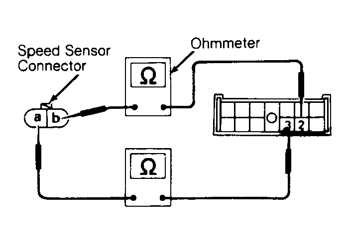 Courtesy of NISSAN MOTOR CO., U.S.A.
- Remove speed sensor from transmission. Turn speedometer pinion quickly and measure voltage across sensor terminals. Voltage should be approximately .5 volt alternating current. If voltage reading is okay, go to next step. If reading is incorrect, replace speed sensor.
- Install speed sensor. Jack up one rear wheel. Turn ignition on. Turn rear wheel by hand and measure voltage between terminal No. 6 and ground. See Figure
. Voltage should change between ZERO volt and approximately .5 volt. If voltage reading is correct, replace speedometer.