Repair procedures
Removal
[RH]
1. Remove the RH bank timing chain.
2. Remove the RH exhaust CVVT oil control valve.
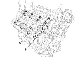
3. Remove the RH camshaft bearing cap (A) and thrust bearing cap (B).
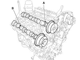
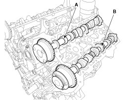
4. Remove the RH intake camshaft (A) and exhaust camshaft (B)
[LH]
1. Remove the RH/LH timing chain.
2. Remove the LH exhaust CVVT oil control valve.
3. Remove the fuel pump bracket (A)
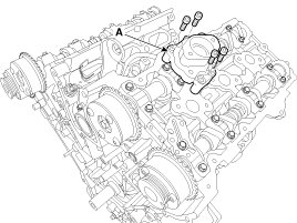
4. Remove the LH camshaft bearing cap (A) and thrust bearing cap (B).
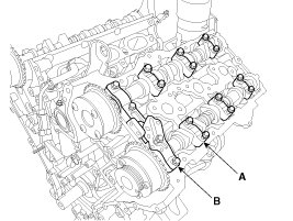
5. Remove the LH intake camshaft (A) and exhaust camshaft (B)
Installation
CAUTION:
- Apply a light coat of engine oil on camshaft journals.
- Assemble the key groove of camshaft rear side to the same level of head top surface.
- Be careful the right, left bank, intake, exhaust side before assembling.
[RH]
1. Install the RH intake camshaft (A) and exhaust camshaft (B)
RH Inkate camshaft
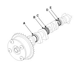
As for camshaft identification, refer to the table below.

RH Exhaust camshaft
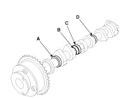
As for camshaft identification, refer to the table below.

2. Install the bearing cap (A) and thrust bearing cap (B) with specified torque.
Tightening torque :
1st step : 5.8N.m (0.6kgf.m, 4.3lb-ft)
2nd step : 9.8 - 11.8N.m (1.0 - 1.2kgf.m, 7.2 - 8.7lb-ft)
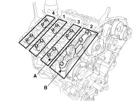
CAUTION:
Be sure to install the thrust bearing cap bolts and the bearing cap bolts in the correct place.
NOTE:
Be careful the right, left bank, intake, exhaust side before assembling.
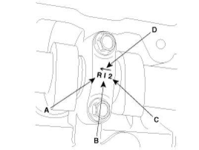
A : L(LH),R(RH)
B : I(Intake), None(Exhaust)
C : Journal number
D : Front mark
CAUTION:
Rotate the crankshaft not to contact the valves to the pistons by making the pistons below 10mm(0.3937in.) from the top of cylinder block.
3. Install the other parts reverse order of removal.
[LH]
1. Install the LH intake camshaft (A) and exhaust camshaft (B)
LH Inkate camshaft
As for camshaft identification, refer to the table below.

NOTE:
The LH intake camshaft doesn't have identification ring.
LH Exhaust camshaft
As for camshaft identification, refer to the table below.

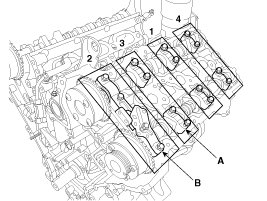
2. Install the bearing cap (A) and thrust bearing cap (B) with specified torque.
Tightening torque :
1st step : 5.8N.m (0.6kgf.m, 4.3lb-ft)
2nd step : 9.8 - 11.8N.m (1.0 - 1.2kgf.m, 7.2 - 8.7lb-ft)
CAUTION:
Be sure to install the thrust bearing cap bolts and the bearing cap bolts in the correct place.
NOTE:
Be careful the right, left bank, intake, exhaust side before assembling.
A : L(LH),R(RH)
B : I(Intake), None(Exhaust)
C : Journal number
D : Front mark
CAUTION:
Rotate the crankshaft not to contact the valves to the pistons by making the pistons below 10mm(0.3937in.) from the top of cylinder block.
3. Install the fuel pump bracket (A)
Tightening torque :
18.6 - 23.5 N.m (1.9 - 2.4 kgf.m, 13.7 - 17.4 lb-ft)
4. Install the other parts reverse order of removal.