Fuel System
General Description
A communication line exists between the Engine Control Module(PCM) and the Transaxle Control Module(TCM). The communication is through a Control Area Network(CAN). Without CAN communication, an independent pin and wiring is needed to receive a sensor information from a PCM. The more information to be communicated, the more wirings is required. In case of CAN communication type, all the information need to be communicated among control modules such as PCM and ABS control module use CAN lines.
DTC Description
The PCM determines CAN communication error and sets DTC U0001 if communication with other control devices (e.g. ABS) via CAN is impossible or PCM detects that communication time via CAN exceeds threshold value.
DTC Detecting Condition
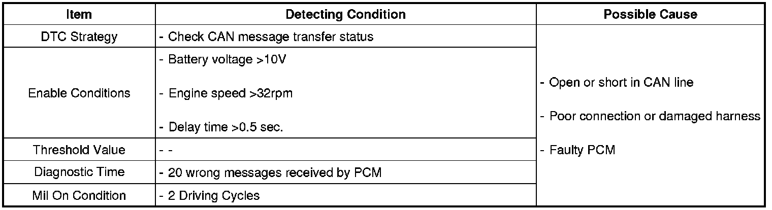
Diagnostic Circuit Diagram
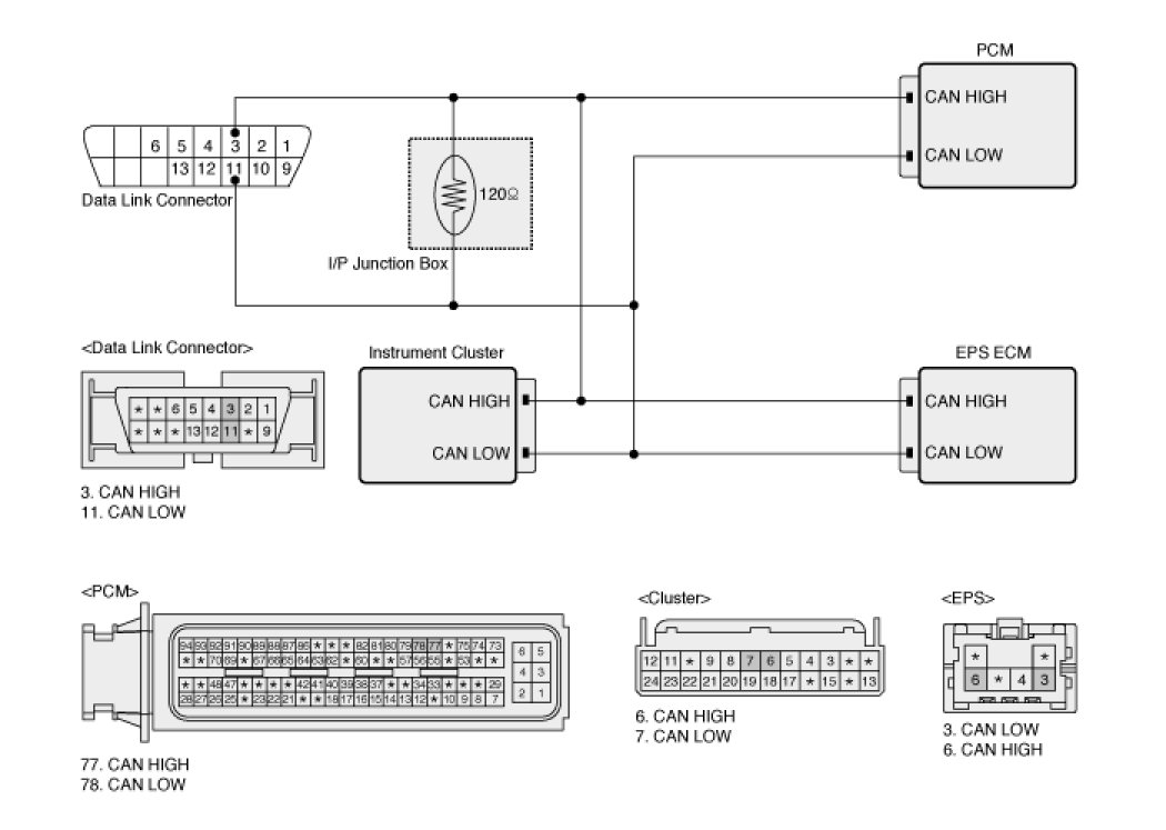
Signal Waveform & Data
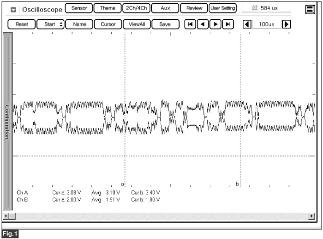
Fig 1) Normal waveform with ignition ON
Monitor DTC Status
1. Connect GDS and select "Diagnostic Trouble Codes(DTCs)" mode
2. Click "DTC Status" on the menu bar to see DTC's information.
3. Confirm that "DTC Readiness Flag" indicates "Complete". If not, drive the vehicle within conditions noted in the freeze frame data or enable conditions.
4. Read "DTC Status" parameter.
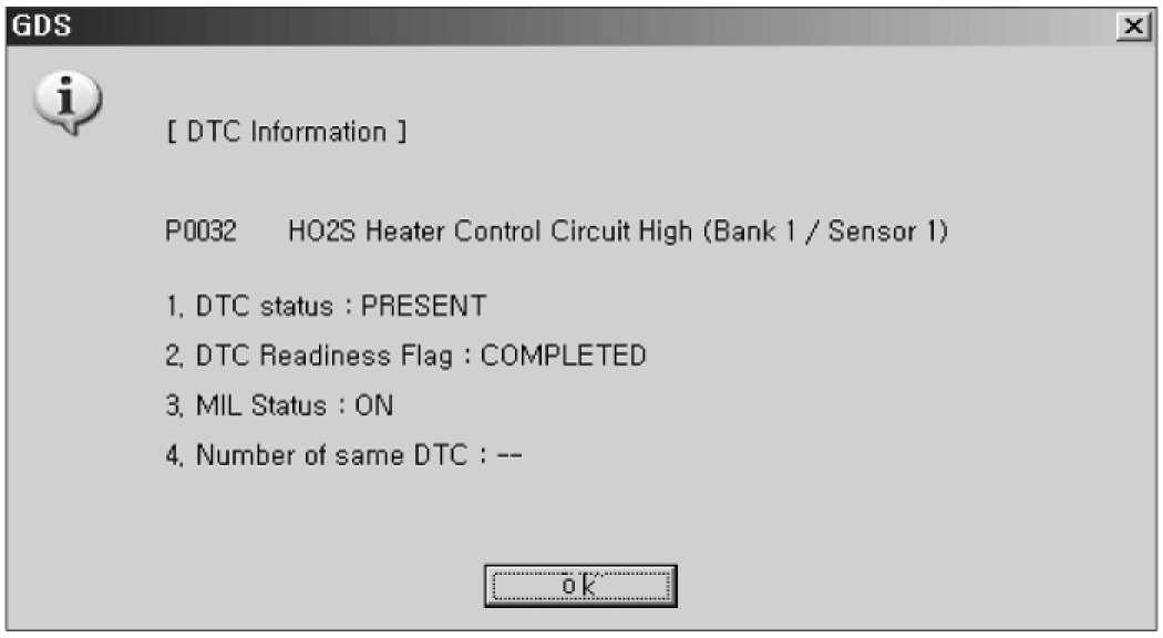
5. Is parameter displayed "History(Not Present) fault"?
NOTE:
- History (Not Present) fault : DTC occurred but has been cleared.
- Present fault : DTC is occurring at present time.

Check CAN communication line for open
1. Ignition "OFF"
2. Disconnect PCM harness connector
3. Measure resistance between High signal terminal and Low signal terminal of PCM harness connector.
Specification :Approx. 110 - 130Ohms
4. Is resistance within the specification?

Check CAN communication line for short to ground
1. Measure resistance between High signal terminal of PCM harness connector and chassis ground.
2. Measure resistance between Low signal terminal of PCM harness connector and chassis ground
Specification :Infinite(above 10kOhms)
3. Is resistance within the specification?

Check CAN communication line for short to battery
1. Disconnect the connectors related to the CAN communication
2. Ignition "ON" & Engine "OFF"
3. Measure voltage between High signal terminal of PCM harness connector and chassis ground.
4. Measure voltage between Low signal terminal of PCM harness connector and chassis ground.
Specification :Approx. 0V
5. Is voltage within the specification?

Terminal and Connector Inspection
1. Many malfunctions in the electrical system are caused by poor harness(es) and terminals. Faults can also be caused by interference from other electrical systems, and mechanical or chemical damage.
2. Thoroughly check connectors for looseness, poor connection, bending, corrosion, contamination, deterioration, or damage.
3. Has a problem been found?

Component Inspection
1. Ignition "OFF"
2. Measure resistance between High signal terminal and Low signal terminal of PCM connector(PCM side).
Specification :Approx. 110 - 130Ohms
3. Is resistance within the specification?

Verification of Vehicle Repair
After a repair, it is essential to verify that the fault has been corrected.
1. Connect GDS and select "Diagnostic Trouble Codes(DTCs)" mode.
2. Press F4(DTAL) and confirm that "DTC Readiness Flag" indicates "Complete". If not, drive the vehicle within conditions noted in the freeze frame data or enable conditions.
3. Read "DTC Status" parameter.
4. Is parameter displayed "History(Not Present) fault"?
