Campaign 078 - Stop Lamp Switch Harness Routing
Group: CAMPAIGNNumber: 06-01-010-1
Date: OCTOBER, 2006
Model:
2007 ENTOURAGE
Subject:
STOP LAMP SWITCH WIRING HARNESS CAMPAIGN 078
This bulletin supersedes TSB # 06-01-010 to include updated service procedure in formation.
IMPORTANT:
DEALERS MUST PERFORM THIS CAMPAIGN ON ALL AFFECTED VEHICLES PRIOR TO CUSTOMER RETAIL DELIVERY AND WHENEVER AN AFFECTED VEHICLE IS IN THE SHOP FOR ANY MAINTENANCE OR REPAIR.
IMPORTANT:
WHEN A VEHICLE ARRIVES AT THE SERVICE DEPARTMENT, ACCESS HYUNDAI MOTOR AMERICA'S "WARRANTY VEHICLE INFORMATION" SCREEN VIA DCS ON-LINE TO IDENTIFY OPEN CAMPAIGNS.
DESCRIPTION:
Some 2007 MY Entourage Limited vehicles equipped with the Power Adjustable Brake Pedal feature may have interference between the stop lamp switch wiring harness and the steering column universal joint.
This bulletin describes the procedure to reroute the stop lamp switch wiring harness away from the steering column universal joint.
VEHICLES AFFECTED:
^ Model: 2007 Entourage Limited vehicles equipped with Power Adjustable Brake Pedal.
^ Affected production date range: Start of production through May 17, 2006.
PARTS REQUIRED:

Two (2) nylon Zip Ties approximately 20 cm (~ 8 in) in length and 0.5 cm (0.2 in) in width.
SERVICE PROCEDURE:
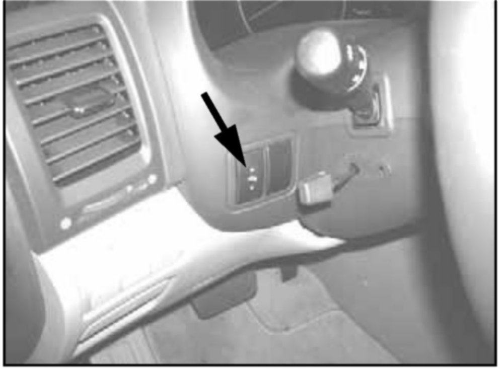
1. Move Power Adjustable Brake Pedal all the way down.
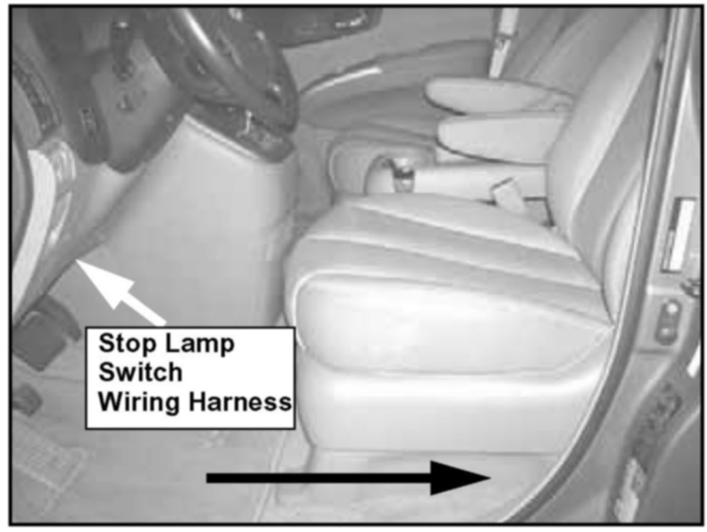
2. Slide the drive's seat all the way back.
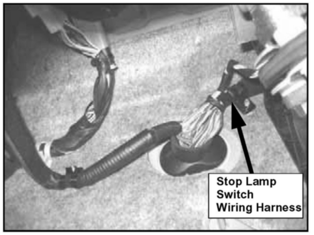
3. Locate the stop lamp switch wiring harness under the instrument panel as shown in photo.
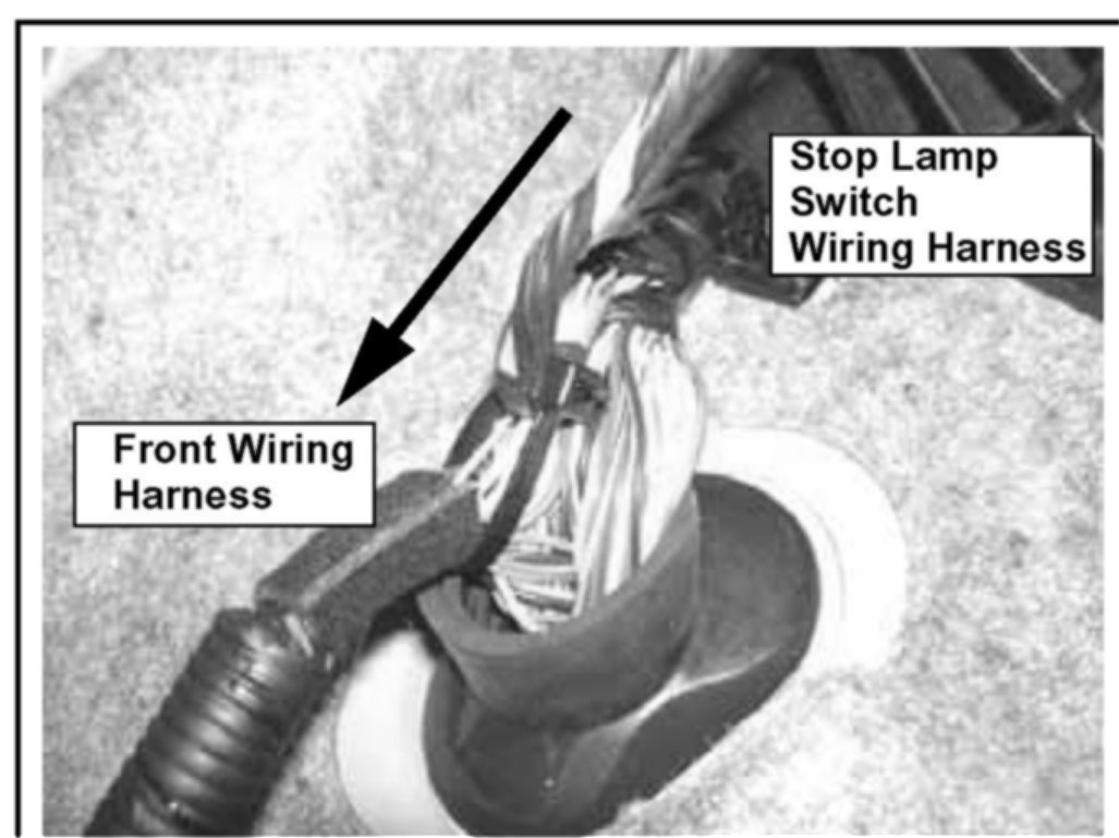
4. Tie the stop lamp switch wiring - harness and the front wiring harness with a plastic zip tie as shown in the photo. This procedure will pull the stop lamp switch wiring harness in the arrow direction to create clearance between the harness and the steering column shaft.
5. Cut off the excess plastic zip tie. Be careful not to damage the vehicle's wiring.
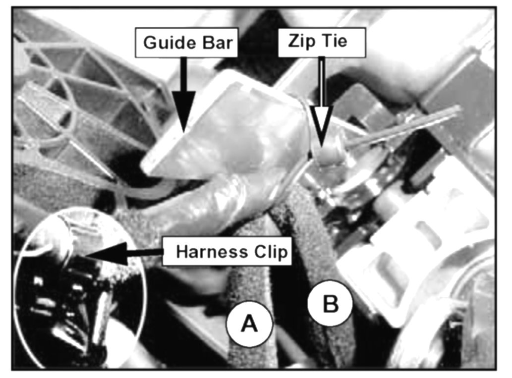
6. Locate the stop lamp switch wiring harness clip above the steering column shaft. At the clip, the harness splits off into two harnesses. Zip tie between the two branches of the harness to the steering column shaft guide bar. This will prevent the zip tie from sliding off the guide bar.
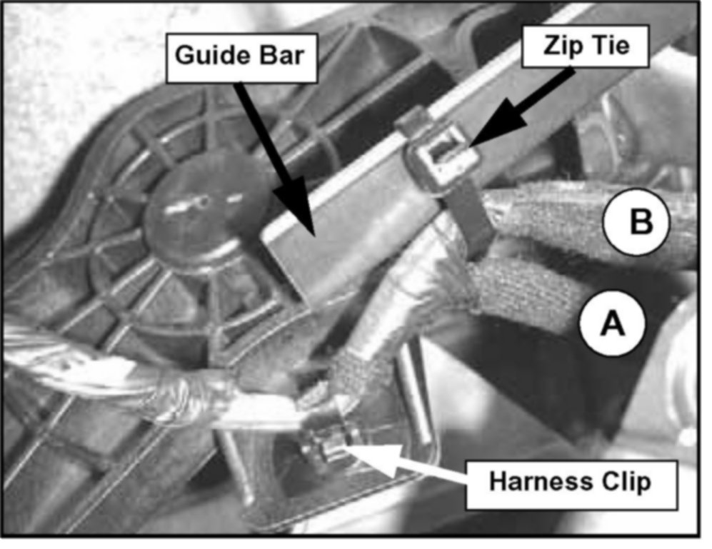
7. Cut off the excess zip tie. Be careful not to damage the vehicle's wiring.
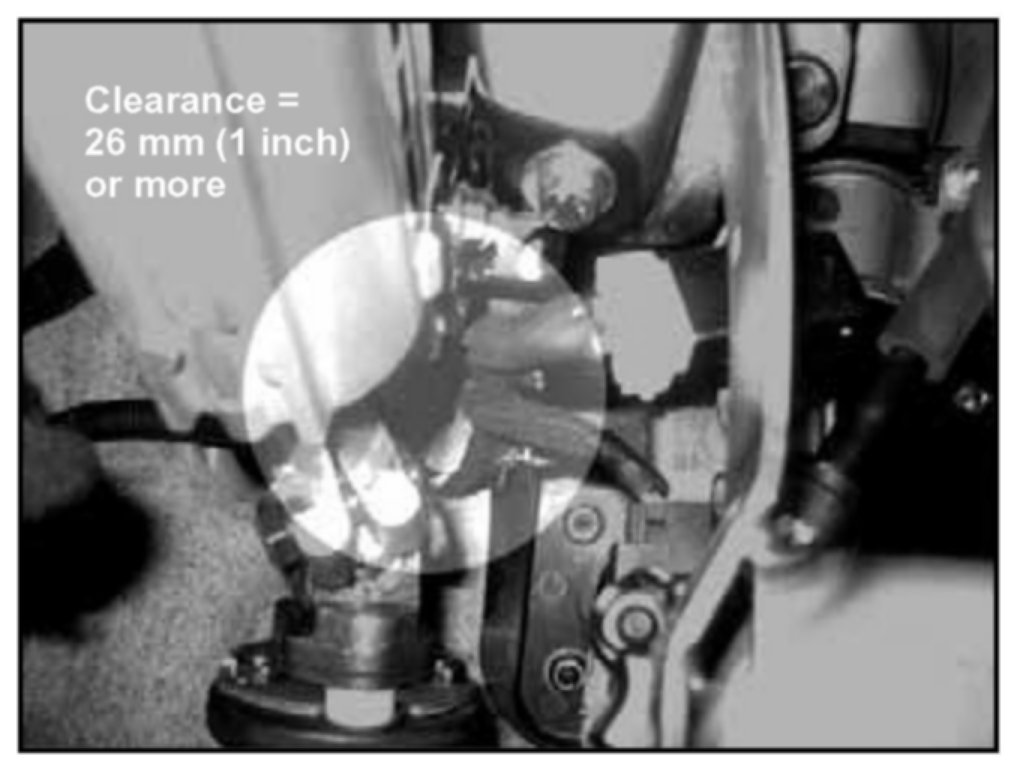
8. Verify that the clearance between the stop lamp switch wiring harness and the steering column shaft and knuckle is 26 mm (~1 inch) or more.

CAMPAIGN CLAIM INFORMATION
NOTE:
Submit claim using the Campaign Claim Screen.