Crankshaft and Piston Removal
- Remove the engine/transmission (see
ENGINE REMOVAL
).
- Remove the transmission (see
TRANSMISSION REMOVAL
).
- Remove the drive plate (see
DRIVE PLATE REMOVAL AND INSTALLATION
).
- Remove the cylinder heads (see
CYLINDER HEAD REMOVAL
).
- Remove the timing belt drive pulley from the crankshaft (see
TIMING BELT DRIVE PULLEY REPLACEMENT
).
- Remove the oil pan (see OIL PAN REMOVAL
).
- Remove the engine block end cover.
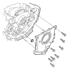 Courtesy of AMERICAN HONDA MOTOR CO., INC.
- Remove the rocker arm oil pressure sensor cover (A), then remove the oil filter base/oil filter assembly (B).
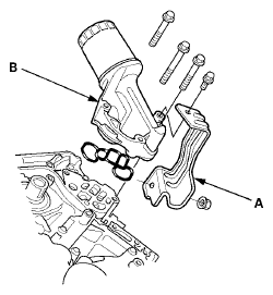 Courtesy of AMERICAN HONDA MOTOR CO., INC.
- Remove the oil strainer (A), the baffle plate (B), and the oil pump (C).
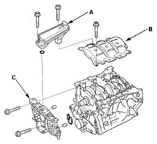 Courtesy of AMERICAN HONDA MOTOR CO., INC.
- If you can feel a ridge of metal or hard carbon around the top of any cylinder, remove it with a ridge reamer (A). Follow the reamer manufacturer's instructions. If the ridge is not removed, it may damage the piston as it's pushed out.
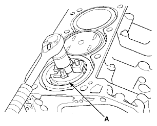 Courtesy of AMERICAN HONDA MOTOR CO., INC.
- Remove the connecting rod caps after setting the connecting rod journal at bottom dead center (BDC) for each cylinder. Remove the piston/connecting rod assembly by pushing on the connecting rod. Take care not to damage the oil jets, the connecting rod journal, or the cylinder with the connecting rod.
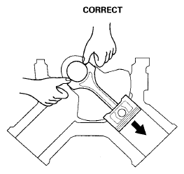 Courtesy of AMERICAN HONDA MOTOR CO., INC.
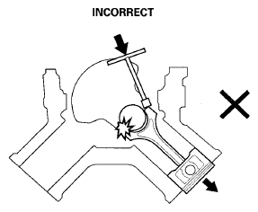 Courtesy of AMERICAN HONDA MOTOR CO., INC.
- Remove the bearing from the rod cap. Keep all caps/bearings in order.
- Remove the upper bearing halves from the connecting rods, and set them aside with their respective caps.
- After removing a piston/connecting rod assembly, reinstall the rod cap on the rod.
- To avoid confusion during reassembly, mark each piston/connecting rod assembly with its cylinder number.
- Loosen the bearing cap bolts and the bearing cap side bolts in sequence 1/3 turn at a time; repeat the sequence until all bolts are loosened.
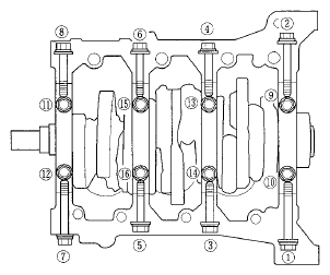 Courtesy of AMERICAN HONDA MOTOR CO., INC.
- Remove the bearing cap bolts (A) and the bearing cap side bolts (B), then remove the bearing caps (C).
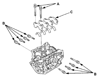 Courtesy of AMERICAN HONDA MOTOR CO., INC.
- Lift the crankshaft (A) out of the engine block, being careful not to damage the journals and the CKP pulse plate.
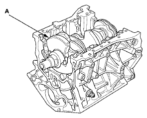 Courtesy of AMERICAN HONDA MOTOR CO., INC.
- Remove the CKP pulse plate from the crankshaft (see CKP PULSE PLATE REPLACEMENT
).
- Reinstall the main caps and the bearings on the engine block in the proper order.