Water Outlet Removal and Installation: Installation
- Remove all of the old liquid gasket from the water outlet mating surfaces, the bolts, and the bolt holes.
- Clean and dry the water outlet mating surfaces.
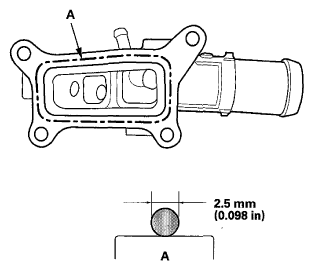
- Apply liquid gasket (P/N 08718-0004) to the cylinder head mating surface of the water outlet and to the inside edge of the bolt holes. Install the component within 5 minutes of applying the liquid gasket.
NOTE:
- Apply a 2.5 mm (0.098 in) diameter bead of liquid gasket along the broken line (A).
- If too much time has passed after applying the liquid gasket, remove the old liquid gasket and residue, then reapply new liquid gasket.
 Courtesy of AMERICAN HONDA MOTOR CO., INC.
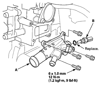
- Install the water outlet (A).
NOTE:
- After assembly, wait at least 30 minutes before filling the engine with coolant.
- Do not run the engine for at least 3 hours after installing the water outlet.
 Courtesy of AMERICAN HONDA MOTOR CO., INC.
- Install ECT sensor 1 (B) with a new O-ring (see
ECT SENSOR 1 REPLACEMENT
).
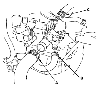
- Connect the upper radiator hose (A), the water bypass hose (B), and the heater hose (C).
 Courtesy of AMERICAN HONDA MOTOR CO., INC.
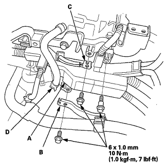
- Install the harness holder (A).
 Courtesy of AMERICAN HONDA MOTOR CO., INC.
- Install the heater hose bracket (B) and the ground cable (C), then connect the water bypass hose (D) to the water outlet.
- Clean up any spilled engine coolant.
- Install the harness clamps (A) with the harness holders (B).
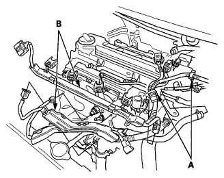 Courtesy of AMERICAN HONDA MOTOR CO., INC.
- Connect the following engine wire harness connectors and wire harness clamps:
- Four injector connectors
- Rocker arm oil control valve connector
- Rocker arm oil pressure switch connector
- ECT sensor 1 connector
- CMP sensor connector
- A/F sensor connector
- Secondary HO2S connector
- Oil pressure switch connector
- Knock sensor connector
- Install the intake manifold/chamber assembly (see
INSTALLATION
).
- Install the throttle body (see
THROTTLE BODY REMOVAL/INSTALLATION
).
- Refill the radiator with engine coolant, and bleed the air from the cooling system (see COOLANT REPLACEMENT
).