STARTER CABLE
| Connector or Terminal |
Ref |
Cavities |
Location |
Connects to |
Notes |
| (+) |
6 |
|
Left side of engine compartment |
Battery positive terminal |
|
| T-1 |
7 |
|
On the battery |
Battery terminal fuse box (see
CONNECTOR TO FUSE/RELAY BOX INDEX
) |
|
| T-6 |
8 |
|
Middle of engine compartment |
Starter solenoid |
|
BATTERY GROUND CABLE
| Connector or Terminal |
Ref |
Cavities |
Location |
Connects to |
Notes |
| (-) |
5 |
|
Left side of engine compartment |
Battery negative terminal |
|
| G1 |
4 |
|
Left side of engine compartment |
Body ground, via battery ground cable |
|
ENGINE GROUND CABLE
| Connector or Terminal |
Ref |
Cavities |
Location |
Connects to |
Notes |
| G2 |
9 |
|
Right side of engine compartment |
Body ground, via engine ground cable |
|
| T-7 |
1 |
|
Right side of engine compartment |
Engine |
|
TRANSMISSION GROUND CABLE
| Connector or Terminal |
Ref |
Cavities |
Location |
Connects to |
Notes |
| G3 |
3 |
|
Left side of engine compartment |
Body ground, via transmission ground cable |
|
| T-8 |
2 |
|
Left side of engine compartment |
Transmission housing |
|
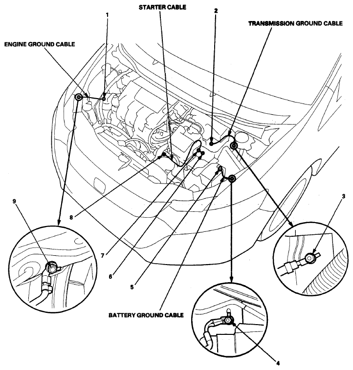 Courtesy of AMERICAN HONDA MOTOR CO., INC.
 ENGINE WIRE HARNESS (ENGINE SECTION)
| Connector or Terminal |
Ref |
Cavities |
Location |
Connects to |
Notes |
| A/F sensor (sensor 1) |
5 |
4 |
Exhaust manifold |
|
|
| CMP sensor |
8 |
3 |
Middle of engine compartment |
|
|
| EGR valve/EGR valve position sensor |
37 |
5 |
Middle of engine compartment |
|
|
| Engine coolant temperature (ECT) sensor 1 |
10 |
2 |
Middle of engine compartment |
|
|
| EVAP canister purge valve |
9 |
2 |
Middle of engine compartment |
|
|
| Knock sensor |
30 |
2 |
Front of engine |
|
|
| MAF sensor/IAT sensor |
14 |
5 |
Middle of engine compartment |
|
|
| MAP sensor |
7 |
3 |
Middle of engine compartment |
|
|
| Motor rotor position sensor |
19 |
6 |
Middle of engine compartment |
|
|
| No. 1 exhaust side ignition coil |
1 |
3 |
Middle of engine compartment |
|
|
| No. 2 exhaust side ignition coil |
2 |
3 |
Middle of engine compartment |
|
|
| No. 3 exhaust side ignition coil |
3 |
3 |
Middle of engine compartment |
|
|
| No. 4 exhaust side ignition coil |
4 |
3 |
Middle of engine compartment |
|
|
| No. 1 injector |
35 |
2 |
Middle of engine compartment |
|
|
| No. 2 injector |
33 |
2 |
Middle of engine compartment |
|
|
| No. 3 injector |
31 |
2 |
Middle of engine compartment |
|
|
| No. 4 injector |
27 |
2 |
Middle of engine compartment |
|
|
| No. 1 intake side ignition coil |
36 |
3 |
Middle of engine compartment |
|
|
| No. 2 intake side ignition coil |
34 |
3 |
Middle of engine compartment |
|
|
| No. 3 intake side ignition coil |
32 |
3 |
Middle of engine compartment |
|
|
| No. 4 intake side ignition coil |
28 |
3 |
Middle of engine compartment |
|
|
| Oil pressure switch |
29 |
1 |
Front of engine |
|
|
| PCM connector B |
18 |
49 |
Left of engine compartment |
|
|
| PCM connector C |
17 |
49 |
Left of engine compartment |
|
|
| Secondary HO2S (sensor 2) |
6 |
4 |
Exhaust manifold |
|
|
| Starter |
24 |
1 |
Middle of engine compartment |
|
|
| Throttle body |
12 |
6 |
Middle of engine compartment |
|
|
| S1 (Thermal joint) |
13 |
|
Middle of engine compartment |
|
|
| S2 (Thermal joint) |
20 |
|
Middle of engine compartment |
|
|
| S3 (Thermal joint) |
21 |
|
Middle of engine compartment |
|
|
| S4 (Thermal joint) |
22 |
|
Middle of engine compartment |
|
|
| C101 |
11 |
3 |
Middle of engine compartment |
CKP Sensor subharness |
|
| C102 |
15 |
12 |
Left of engine compartment |
Left engine compartment wire harness (see Left Engine Compartment Wire Harness (Engine compartment branch)
) |
|
| C103 |
16 |
13 |
Left of engine compartment |
Left engine compartment wire harness (see Left Engine Compartment Wire Harness (Engine compartment branch)
) |
|
| C104 (Junction connector) |
23 |
24 |
Middle of engine compartment |
|
|
| C105 (Junction connector) |
25 |
24 |
Middle of engine compartment |
|
|
| G101 |
26 |
|
Middle of engine compartment |
Body ground, via engine wire harness |
|
CKP SENSOR SUBHARNESS
| Connector or Terminal |
Ref |
Cavities |
Location |
Connects to |
Notes |
| CKP sensor |
38 |
3 |
Under the engine |
|
|
| C101 |
11 |
3 |
Middle of engine compartment |
Engine wire harness |
|
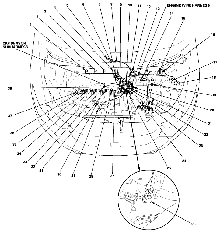 Courtesy of AMERICAN HONDA MOTOR CO., INC.
 ENGINE WIRE HARNESS (TRANSMISSION SECTION)
| Connector or Terminal |
Ref |
Cavities |
Location |
Connects to |
Notes |
| CVT input (drive pulley) speed sensor |
5 |
3 |
Transmission housing |
|
|
| CVT output (driven pulley) speed sensor |
3 |
3 |
Transmission housing |
|
|
| CVT speed sensor |
1 |
3 |
Transmission housing |
|
|
| Driven pulley pressure sensor |
4 |
3 |
Transmission housing |
|
|
| Rocker arm oil control solenoid A |
13 |
2 |
Transmission housing |
|
|
| Rocker arm oil control solenoid B |
14 |
2 |
Transmission housing |
|
|
| Rocker arm oil pressure sensor A |
15 |
3 |
Transmission housing |
|
|
| Rocker arm oil pressure sensor B |
16 |
3 |
Transmission housing |
|
|
| Transmission range switch |
2 |
8 |
Side of transmission housing |
|
|
| C106 |
6 |
8 |
On transmission housing |
Shift solenoid wire harness |
|
SHIFT SOLENOID WIRE HARNESS
| Connector or Terminal |
Ref |
Cavities |
Location |
Connects to |
Notes |
| CVT drive pulley pressure control solenoid valve |
7 |
2 |
In the transmission |
|
|
| CVT driven pulley pressure control solenoid valve |
9 |
2 |
In the transmission |
|
|
| CVT clutch pressure control solenoid valve |
8 |
2 |
In the transmission |
|
|
| CVTF temperature sensor |
11 |
|
In the transmission |
|
|
| Inhibitor solenoid |
10 |
2 |
In the transmission |
|
|
| C106 |
6 |
7 |
On transmission housing |
Engine wire harness |
|
| G151 |
12 |
|
In the transmission |
Body ground, via shift solenoid wire harness |
|
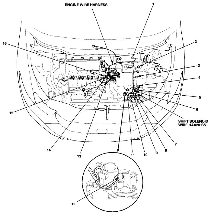 Courtesy of AMERICAN HONDA MOTOR CO., INC.
 RIGHT ENGINE COMPARTMENT WIRE HARNESS (ENGINE COMPARTMENT BRANCH)
| Connector or Terminal |
Ref |
Cavities |
Location |
Connects to |
Notes |
| Right front turn signal light |
6 |
2 |
Behind right side of front bumper |
|
|
| Outside air temperature sensor |
4 |
2 |
Behind right side of front bumper |
|
|
| Right front impact sensor |
9 |
2 |
Behind right side of front bumper |
|
|
| Right front parking light |
2 |
2 |
Behind right headlight |
|
|
| Right front wheel speed sensor |
13 |
2 |
Right side of engine compartment |
|
|
| Right headlight (HIGH) |
3 |
2 |
Behind right headlight |
|
|
| Right headlight (LOW) |
1 |
2 |
Behind right headlight |
|
|
| Right front side marker light |
10 |
2 |
Behind right headlight |
|
|
| VSA modulator-control unit |
11 |
47 |
Right side of engine compartment |
|
|
| Washer fluid level switch |
8 |
2 |
Behind right side of front bumper |
|
Canada model |
| Windshield/rear window washer motor |
7 |
2 |
Behind right side of front bumper |
|
|
| G202 |
5 |
|
Behind right side of front bumper |
Body ground, via right engine compartment wire harness |
|
| G203 (for VSA) |
12 |
|
Right side of engine compartment |
Body ground, via right engine compartment wire harness |
|
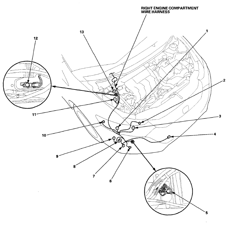 Courtesy of AMERICAN HONDA MOTOR CO., INC.
 RIGHT ENGINE COMPARTMENT WIRE HARNESS (DASH BRANCH)
| Connector or Terminal |
Ref |
Cavities |
Location |
Connects to |
Notes |
| Evaporator temperature sensor |
4 |
2 |
Under right side of dash |
|
|
| Under-dash fuse/relay box connector A (see
FUSE TO COMPONENTS INDEX
) |
5 |
36 |
Under left side of dash |
|
|
| C201 |
3 |
16 |
Under right side of dash |
Dashboard wire harness (see Dashboard Wire Harness (View of passenger's side)
) |
|
| C202 |
2 |
4 |
Under right side of dash |
Dashboard wire harness (see Dashboard Wire Harness (View of passenger's side)
) |
|
| C304 |
1 |
13 |
Under left side of dash |
Left engine compartment wire harness (see Left Engine Compartment Wire Harness (Dash branch)
) |
|
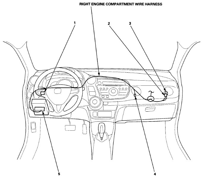 Courtesy of AMERICAN HONDA MOTOR CO., INC.
 LEFT ENGINE COMPARTMENT WIRE HARNESS (ENGINE COMPARTMENT BRANCH)
| Connector or Terminal |
Ref |
Cavities |
Location |
Connects to |
Notes |
| A/C compressor |
35 |
3 |
Behind right side of front bumper |
|
|
| A/C compressor clutch relay |
27 |
4 |
In the auxiliary under-hood relay box (see
FUSE TO COMPONENTS INDEX
) |
|
|
| A/C condenser fan motor |
37 |
2 |
Front of engine compartment |
|
|
| A/C condenser fan relay |
30 |
4 |
In the auxiliary under-hood relay box (see
FUSE TO COMPONENTS INDEX
) |
|
|
| A/C pressure sensor |
36 |
3 |
Behind right side of front bumper |
|
|
| A/C diode A |
28 |
2 |
In the auxiliary under-hood relay box (see
FUSE TO COMPONENTS INDEX
) |
|
|
| A/C diode B |
29 |
2 |
In the auxiliary under-hood relay box (see
FUSE TO COMPONENTS INDEX
) |
|
|
| Brake booster pressure sensor A |
6 |
3 |
Middle of engine compartment |
|
|
| Brake booster pressure sensor B |
5 |
3 |
Middle of engine compartment |
|
|
| Torque sensor |
7 |
4 |
Middle of engine compartment |
|
|
| EPS motor |
8 |
2 |
Middle of engine compartment |
|
|
| Left front wheel speed sensor |
13 |
2 |
Left of engine compartment |
|
|
| Brake fluid level switch |
14 |
2 |
Left of engine compartment |
|
|
| PCM connector A |
15 |
49 |
Left of engine compartment |
|
|
| Left front parking light |
25 |
2 |
Behind left headlight |
|
|
| Left headlight (HIGH) |
24 |
2 |
Behind left headlight |
|
|
| Fan control relay |
17 |
5 |
In the auxiliary under-hood fuse/relay box (see
FUSE TO COMPONENTS INDEX
) |
|
|
| Left front side marker light |
19 |
2 |
Behind left headlight |
|
|
| Left headlight (LOW) |
20 |
2 |
Behind left headlight |
|
|
| Left front impact sensor |
21 |
2 |
Behind left side of front bumper |
|
|
| Left front turn signal light |
23 |
2 |
Behind left side of front bumper |
|
|
| Optional connector (for fog light) |
16 |
1 |
Left of engine compartment |
|
|
| Engine coolant temperature (ECT) sensor 2 |
34 |
2 |
Behind right side of front bumper |
|
|
| Radiator fan motor |
31 |
2 |
Front of engine compartment |
|
|
| Security hood switch |
33 |
2 |
Front of engine compartment |
|
With security |
| Horn |
1 |
1 |
Front of engine compartment |
|
|
| Radiator fan relay |
26 |
4 |
In the auxiliary under-hood relay box (see
FUSE TO COMPONENTS INDEX
) |
|
|
| PGM-FI main relay 2 |
18 |
4 |
In the auxiliary under-hood fuse/relay box (see
FUSE TO COMPONENTS INDEX
) |
|
|
| C102 |
9 |
12 |
Left of engine compartment |
Engine wire harness (see Engine Wire Harness (Engine section)
) |
|
| C103 |
10 |
13 |
Left of engine compartment |
Engine wire harness (see Engine Wire Harness (Engine section)
) |
|
| C301 |
12 |
4 |
Left of engine compartment |
Windshield wiper motor subharness |
|
| T-3 |
2 |
|
On battery |
Battery terminal fuse box (see
CONNECTOR TO FUSE/RELAY BOX INDEX
) |
|
| T-4 |
3 |
|
On battery |
Battery terminal fuse box (see
CONNECTOR TO FUSE/RELAY BOX INDEX
) |
|
| T-5 |
4 |
|
On battery |
Battery terminal fuse box (see
CONNECTOR TO FUSE/RELAY BOX INDEX
) |
|
| G401 |
22 |
|
Behind left side of front bumper |
Body ground, via left engine compartment wire harness |
|
| G404 |
32 |
|
Front of engine compartment |
Body ground, via left engine compartment wire harness |
|
WINDSHIELD WIPER MOTOR SUBHARNESS
| Connector or Terminal |
Ref |
Cavities |
Location |
Connects to |
Notes |
| Windshield wiper motor |
11 |
5 |
Left of engine compartment |
|
|
| C301 |
12 |
4 |
Left of engine compartment |
Left engine compartment wire harness |
|
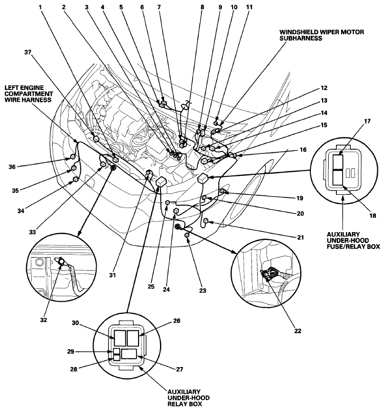 Courtesy of AMERICAN HONDA MOTOR CO., INC.
 LEFT ENGINE COMPARTMENT WIRE HARNESS (DASH BRANCH)
| Connector or Terminal |
Ref |
Cavities |
Location |
Connects to |
Notes |
| APP sensor A/B |
8 |
6 |
Under middle of dash |
|
|
| Brake pedal position switch |
9 |
4 |
Under left side of dash |
|
|
| EPS control unit connector A |
5 |
2 |
Under middle of dash |
|
|
| EPS control unit connector B |
6 |
2 |
Under middle of dash |
|
|
| EPS control unit connector C |
7 |
16 |
Under middle of dash |
|
|
| Idle stop switch |
10 |
2 |
Under left side of dash |
|
|
| Optional connector (for fog light) |
11 |
3 |
Under left side of dash |
|
|
| Under-dash fuse/relay box connector B (see
FUSE TO COMPONENTS INDEX
) |
15 |
36 |
Under left side of dash |
|
|
| C302 |
12 |
20 |
Under left side of dash |
Dashboard wire harness (see Dashboard Wire Harness (View of driver's side)
) |
|
| C303 |
13 |
4 |
Under left side of dash |
Dashboard wire harness (see Dashboard Wire Harness (View of driver's side)
) |
|
| C304 |
17 |
13 |
Under left side of dash |
Right engine compartment wire harness (see Right Engine Compartment Wire Harness (Dash branch)
) |
|
| C305 |
16 |
16 |
Under left side of dash |
Driver's side wire harness (see Driver's Side Wire Harness
) |
|
| C306 (Junction connector) |
2 |
12 |
Under left side of dash |
|
|
| C307 (Junction connector) |
1 |
12 |
Under left side of dash |
|
|
| T-9 |
14 |
|
Under left side of dash |
Under-dash fuse/relay box (see
FUSE TO COMPONENTS INDEX
) |
|
| G402 |
4 |
|
Under left side of dash |
Body ground, via left engine compartment wire harness |
|
| G403 |
3 |
|
Under left side of dash |
Body ground, via left engine compartment wire harness |
|
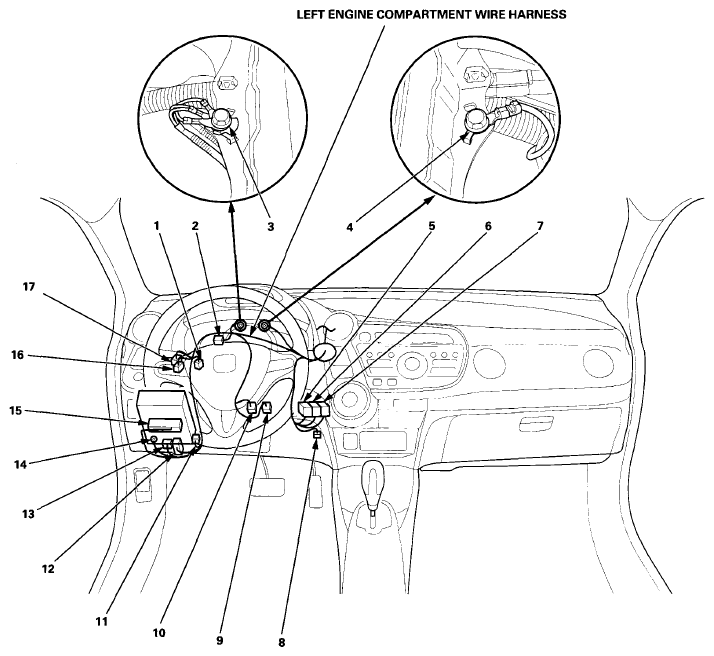 Courtesy of AMERICAN HONDA MOTOR CO., INC.
 DASHBOARD WIRE HARNESS (VIEW OF DRIVER'S SIDE)
| Connector or Terminal |
Ref |
Cavities |
Location |
Connects to |
Notes |
| Cable reel |
8 |
20 |
In steering column |
|
|
| Combination light switch |
7 |
12 |
In steering column |
|
|
| Driver's airbag inflator |
9 |
4 |
In steering column |
|
|
| ECON switch |
15 |
5 |
Left side of dash |
|
|
| Gauge control module |
5 |
32 |
Behind gauge |
|
|
| Hatch release actuator relay |
17 |
5 |
In the under-dash relay holder (see
FUSE TO COMPONENTS INDEX
) |
|
|
| Ignition switch |
13 |
7 |
In steering column |
|
|
| Immobilizer-keyless control unit |
11 |
7 |
In steering column |
|
|
| Left front tweeter |
1 |
2 |
Left side of dash |
|
With front tweeter |
| Power mirror switch |
6 |
13 |
Left side of dash |
|
|
| Steering angle sensor |
14 |
5 |
In steering column |
|
|
| Steering lock assembly (Ignition key switch/key interlock solenoid) |
12 |
6 |
In steering column |
|
|
| Under-dash fuse/relay box connector K (see
FUSE TO COMPONENTS INDEX
) |
26 |
10 |
Under left side of dash |
|
|
| Under-dash fuse/relay box connector M (see
FUSE TO COMPONENTS INDEX
) |
27 |
34 |
Under left side of dash |
|
|
| Under-dash fuse/relay box connector N (see
FUSE TO COMPONENTS INDEX
) |
18 |
8 |
Under left side of dash |
|
|
| Under-dash fuse/relay box connector P (see
FUSE TO COMPONENTS INDEX
) |
25 |
4 |
Under left side of dash |
|
|
| Under-dash fuse/relay box connector Q (see
FUSE TO COMPONENTS INDEX
) |
24 |
16 |
Under left side of dash |
|
|
| Under-dash fuse/relay box connector S (see
FUSE TO COMPONENTS INDEX
) |
19 |
3 |
Under left side of dash |
|
|
| Under-dash fuse/relay box connector T (see
FUSE TO COMPONENTS INDEX
) |
20 |
2 |
Under left side of dash |
|
|
| Under-dash fuse/relay box connector W (see
FUSE TO COMPONENTS INDEX
) |
23 |
1 |
Under left side of dash |
|
|
| Under-dash fuse/relay box connector X (see
FUSE TO COMPONENTS INDEX
) |
22 |
3 |
Under left side of dash |
|
|
| Under-dash fuse/relay box connector Y (see
FUSE TO COMPONENTS INDEX
) |
21 |
3 |
Under left side of dash |
|
|
| VSA OFF switch |
16 |
5 |
Left side of dash |
|
|
| Wiper/washer switch |
10 |
8 |
In steering column |
|
|
| C302 |
31 |
20 |
Under left side of dash |
Left engine compartment wire harness (see Left Engine Compartment Wire Harness (Dash branch)
) |
|
| C303 |
32 |
4 |
Under left side of dash |
Left engine compartment wire harness (see Left Engine Compartment Wire Harness (Dash branch)
) |
|
| C401 |
30 |
4 |
Under left side of dash |
Roof wire harness (see Roof Wire Harness
) |
|
| C402 |
29 |
13 |
Under left side of dash |
Driver's side wire harness (see Driver's Side Wire Harness
) |
|
| C403 |
28 |
18 |
Under left side of dash |
Driver's door wire harness (see Driver's Door Wire Harness
) |
|
| S5 (Thermal joint) |
2 |
|
Under left side of dash |
|
|
| S6 (Thermal joint) |
3 |
|
Under left side of dash |
|
|
| G501 |
4 |
|
Under left side of dash |
Body ground, via dashboard wire harness |
|
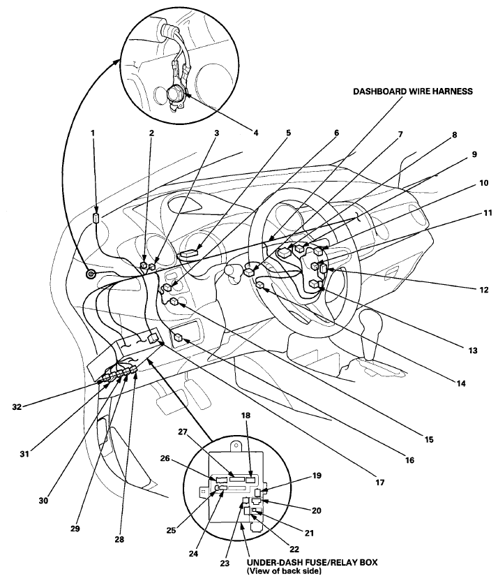 Courtesy of AMERICAN HONDA MOTOR CO., INC.
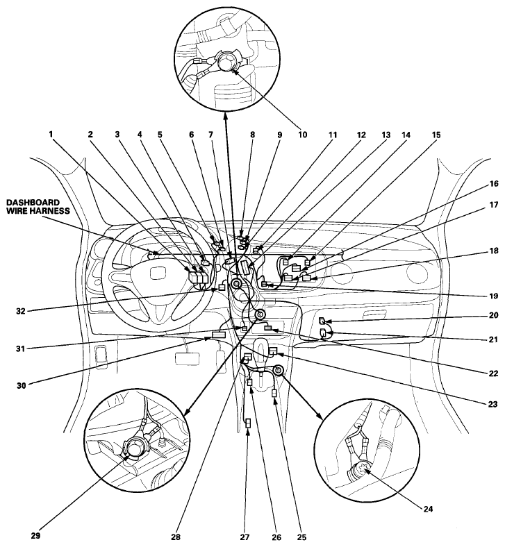
 DASHBOARD WIRE HARNESS (VIEW OF MIDDLE SECTION) (WITH NAVIGATION)
| Connector or Terminal |
Ref |
Cavities |
Location |
Connects to |
Notes |
| Accessory power socket |
31 |
2 |
Middle of dash |
|
|
| Audio-Navigation unit connector A |
17 |
24 |
Middle of dash |
|
|
| Audio-Navigation unit connector B |
16 |
16 |
Middle of dash |
|
|
| Audio-Navigation unit connector C |
15 |
20 |
Middle of dash |
|
|
| Audio-Navigation unit connector D |
14 |
12 |
Middle of dash |
|
|
| Audio-Navigation unit connector E |
18 |
14 |
Middle of dash |
|
With USB adapter |
| Auxiliary jack assembly |
22 |
5 |
Middle of dash |
|
|
| Climate control unit |
7 |
5 |
Middle of dash |
|
|
| Climate control unit |
13 |
36 |
Middle of dash |
|
|
| Data link connector |
30 |
16 |
Under middle of dash |
|
|
| Front passenger's airbag cutoff indicator |
19 |
4 |
Middle of dash |
|
|
| Hazard warning switch |
12 |
5 |
Middle of dash |
|
|
| Humidity/in-car temperature sensor |
32 |
4 |
Middle of dash |
|
|
| Shift lock solenoid/park pin switch/AT gear position indicator panel light |
25 |
6 |
Under center console |
|
|
| SRS unit connector A |
28 |
39 |
Under middle of dash |
|
|
| TPMS control unit |
4 |
20 |
Under middle of dash |
|
Except Canada model |
| Yaw rate-acceleration sensor |
23 |
4 |
Under middle of dash |
|
|
| C404 |
20 |
2 |
Under middle of dash |
A/C wire harness (see A/C Wire Harness
) |
|
| C405 |
21 |
16 |
Under middle of dash |
A/C wire harness (see A/C Wire Harness
) |
|
| C406 |
26 |
12 |
Under center console |
USB unit subharness (see USB Unit Subharness (factory-installed)
) |
With USB adapter |
| C407 |
27 |
23 |
Under center console |
Floor wire harness (see Floor Wire Harness (Right Branch)
) |
|
| C408 (Junction connector) |
1 |
12 |
Under middle of dash |
|
|
| C409 (Junction connector) |
2 |
12 |
Under middle of dash |
|
|
| C410 (Junction connector) |
3 |
12 |
Under middle of dash |
|
|
| S7 (Thermal joint) |
5 |
|
Under middle of dash |
|
|
| S8 (Thermal joint) |
6 |
|
Under middle of dash |
|
|
| S9 (Thermal joint) |
8 |
|
Under middle of dash |
|
|
| S10 (Thermal joint) |
9 |
|
Under middle of dash |
|
|
| S11 (Thermal joint) |
11 |
|
Under middle of dash |
|
|
| G502 |
10 |
|
Under middle of dash |
Body ground, via dashboard wire harness |
|
| G503 |
29 |
|
Under middle of dash |
Body ground, via dashboard wire harness |
|
| G504 |
24 |
|
Under center console |
Body ground, via dashboard wire harness |
|
 Courtesy of AMERICAN HONDA MOTOR CO., INC.
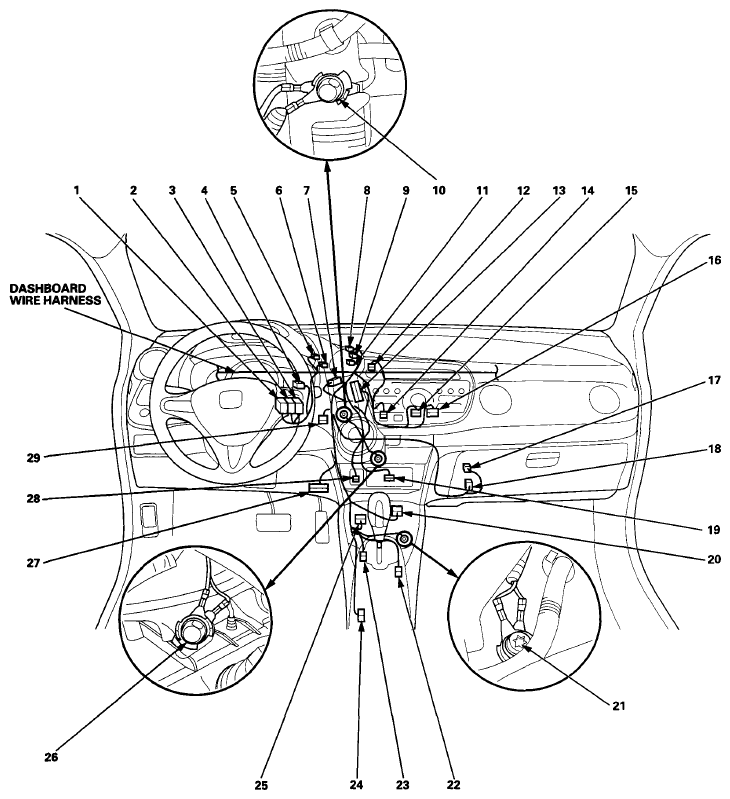
 DASHBOARD WIRE HARNESS (VIEW OF MIDDLE SECTION) (WITHOUT NAVIGATION)
| Connector or Terminal |
Ref |
Cavities |
Location |
Connects to |
Notes |
| Accessory power socket |
28 |
2 |
Middle of dash |
|
|
| Audio unit connector A |
16 |
24 |
Middle of dash |
|
|
| Audio unit connector A |
16 |
17 |
Middle of dash |
|
|
| Audio unit connector B |
15 |
20 |
Middle of dash |
|
|
| Audio unit connector E |
15 |
14 |
Middle of dash |
|
With USB adapter |
| Auxiliary jack assembly |
19 |
5 |
Middle of dash |
|
|
| Climate control unit |
7 |
5 |
Middle of dash |
|
|
| Climate control unit |
13 |
36 |
Middle of dash |
|
|
| Data link connector |
27 |
16 |
Under middle of dash |
|
|
| Front passenger's airbag cutoff indicator |
14 |
4 |
Middle of dash |
|
|
| Hazard warning switch |
12 |
5 |
Middle of dash |
|
|
| Humidity/in-car temperature sensor |
29 |
4 |
Middle of dash |
|
|
| Shift lock solenoid/park pin switch/AT gear position indicator panel light |
22 |
6 |
Under center console |
|
|
| SRS unit connector A |
25 |
39 |
Under middle of dash |
|
|
| TPMS control unit |
4 |
20 |
Under middle of dash |
|
Except Canada model |
| Yaw rate-acceleration sensor |
20 |
4 |
Under middle of dash |
|
|
| C404 |
17 |
2 |
Under middle of dash |
A/C wire harness (see A/C Wire Harness
) |
|
| C405 |
18 |
16 |
Under middle of dash |
A/C wire harness (see A/C Wire Harness
) |
|
| C406 |
23 |
12 |
Under center console |
USB unit subharness (see USB Unit Subharness (factory-installed)
) |
With USB adapter |
| C407 |
24 |
23 |
Under center console |
Floor wire harness (see Floor Wire Harness (Right Branch)
) |
|
| C408 (Junction connector) |
1 |
12 |
Under middle of dash |
|
|
| C409 (Junction connector) |
2 |
12 |
Under middle of dash |
|
|
| C410 (Junction connector) |
3 |
12 |
Under middle of dash |
|
|
| S7 (Thermal joint) |
5 |
|
Under middle of dash |
|
|
| S8 (Thermal joint) |
6 |
|
Under middle of dash |
|
|
| S9 (Thermal joint) |
8 |
|
Under middle of dash |
|
|
| S10 (Thermal joint) |
9 |
|
Under middle of dash |
|
|
| S11 (Thermal joint) |
11 |
|
Under middle of dash |
|
|
| G502 |
10 |
|
Under middle of dash |
Body ground, via dashboard wire harness |
|
| G503 |
26 |
|
Under middle of dash |
Body ground, via dashboard wire harness |
|
| G504 |
21 |
|
Under center console |
Body ground, via dashboard wire harness |
|
 Courtesy of AMERICAN HONDA MOTOR CO., INC.
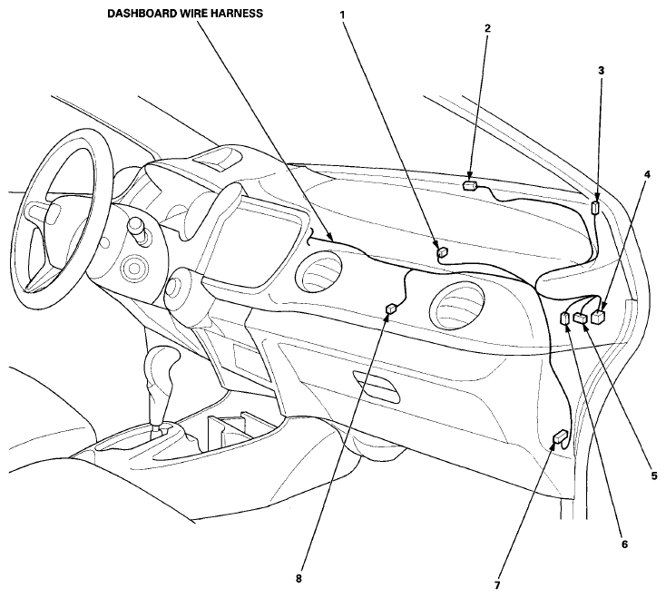
 DASHBOARD WIRE HARNESS (VIEW OF PASSENGER'S SIDE)
| Connector or Terminal |
Ref |
Cavities |
Location |
Connects to |
Notes |
| Front passenger's airbag inflator |
1 |
4 |
Under right side of dash |
|
|
| Glove box light |
8 |
2 |
Under right side of dash |
|
|
| HandsFreeLink control unit |
7 |
32 |
Under right side of dash |
|
|
| HandsFreeLink control unit |
7 |
28 |
Under right side of dash |
|
|
| Right front tweeter |
3 |
2 |
Right side of dash |
|
|
| Automatic lighting sensor/sunlight sensor |
2 |
5 |
Right side of dash |
|
|
| Sunlight sensor |
2 |
2 |
Right side of dash |
|
|
| C411 |
4 |
18 |
Under right side of dash |
Front passenger's door wire harness (see Front Passenger's Door Wire Harness
) |
|
| C201 |
5 |
16 |
Under right side of dash |
Right engine compartment wire harness (see Right Engine Compartment Wire Harness (Dash branch)
) |
|
| C202 |
6 |
4 |
Under right side of dash |
Right engine compartment wire harness (see Right Engine Compartment Wire Harness (Dash branch)
) |
|
 Courtesy of AMERICAN HONDA MOTOR CO., INC.
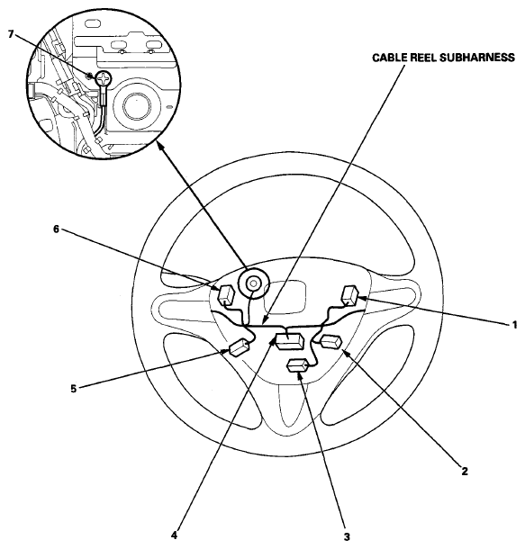
 CABLE REEL SUBHARNESS
| Connector or Terminal |
Ref |
Cavities |
Location |
Connects to |
Notes |
| Cable reel |
4 |
20 |
Steering wheel |
|
|
| HFL-navigation voice control switch |
5 |
5 |
Steering wheel |
|
With navigation |
| Horn switch |
3 |
1 |
Steering wheel |
|
|
| Paddle shifter - (Downshift switch) |
6 |
2 |
Steering wheel |
|
Five-position transmission |
| Paddle shifter + (Upshift switch) |
1 |
2 |
Steering wheel |
|
Five-position transmission |
| Multi-information switch |
2 |
6 |
Steering wheel |
|
With cruise control |
| G551 |
7 |
|
Steering wheel |
|
|
 Courtesy of AMERICAN HONDA MOTOR CO., INC.
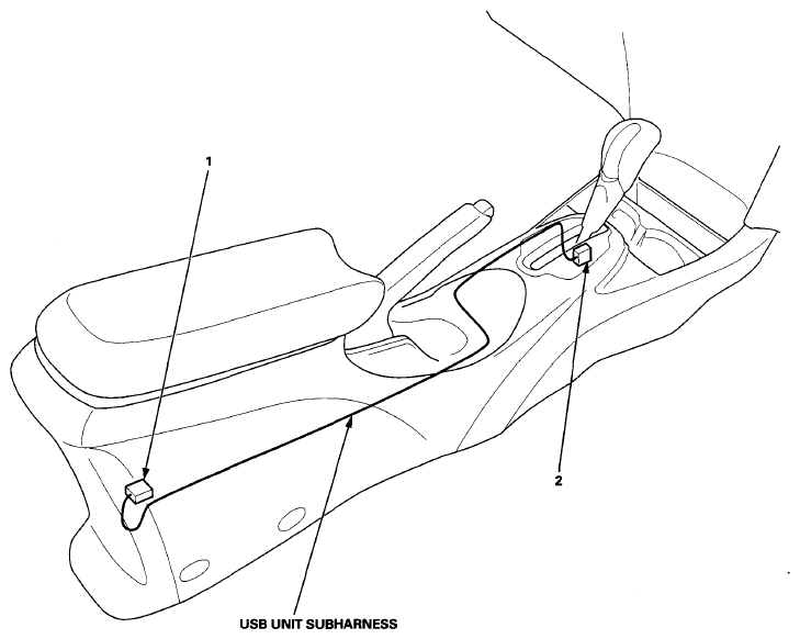
 USB UNIT SUBHARNESS (FACTORY-INSTALLED)
| Connector or Terminal |
Ref |
Cavities |
Location |
Connects to |
Notes |
| USB adapter control unit |
1 |
14 |
Under center console |
|
|
| C406 |
2 |
12 |
Under center console |
Dashboard wire harness (see Dashboard Wire Harness (View of middle section) (With Navigation)
) |
|
| C406 |
2 |
12 |
Under center console |
Dashboard wire harness (see Dashboard Wire Harness (View of middle section) (Without Navigation)
) |
|
 Courtesy of AMERICAN HONDA MOTOR CO., INC.
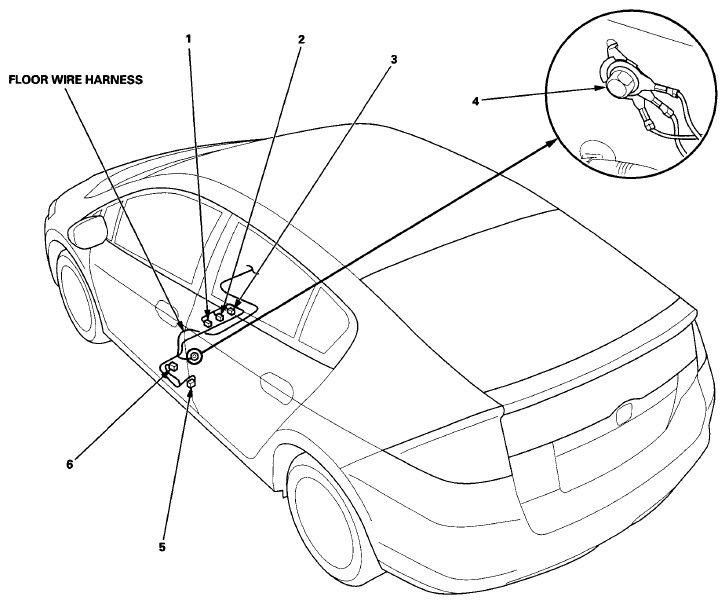
 FLOOR WIRE HARNESS (LEFT BRANCH)
| Connector or Terminal |
Ref |
Cavities |
Location |
Connects to |
Notes |
| Driver's seat belt buckle switch |
3 |
2 |
Under driver's seat |
|
|
| Driver's seat belt tensioner |
5 |
4 |
Left B-pillar |
|
|
| Left side airbag inflator |
1 |
2 |
Under driver's seat |
|
|
| Left side impact sensor (first) |
6 |
4 |
Left B-pillar |
|
|
| C504 |
2 |
3 |
Under driver's seat |
Driver's seat position sensor subharness (see Driver's Seat Position Sensor Subharness
) |
|
| G602 |
4 |
|
Left side of floor |
Body ground, via floor wire harness |
|
 Courtesy of AMERICAN HONDA MOTOR CO., INC.
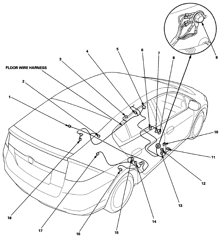
 FLOOR WIRE HARNESS (RIGHT BRANCH)
| Connector or Terminal |
Ref |
Cavities |
Location |
Connects to |
Notes |
| Front passenger's door switch |
10 |
1 |
Right B-pillar |
|
|
| Front passenger's seat belt buckle switch |
6 |
2 |
Under front passenger's seat |
|
|
| Front passenger's seat belt tensioner |
13 |
4 |
Right B-pillar |
|
|
| Fuel tank unit (fuel pump/fuel gauge sending unit) |
18 |
4 |
Under floor |
|
|
| Parking brake switch |
3 |
1 |
Under center console |
|
|
| Right rear door switch |
15 |
1 |
Right C-pillar |
|
|
| Right rear wheel speed sensor |
16 |
2 |
Under floor |
|
|
| Right side airbag inflator |
8 |
2 |
Under front passenger's seat |
|
|
| Right side curtain airbag inflator |
17 |
2 |
Right C-pillar |
|
|
| Right side impact sensor (first) |
11 |
4 |
Right B-pillar |
|
|
| Right side impact sensor (second) |
14 |
2 |
Right C-pillar |
|
|
| SRS unit connector B |
5 |
39 |
Under middle of dash |
|
|
| Rear safing sensor |
2 |
2 |
Under floor |
|
|
| C501 |
1 |
4 |
Under floor |
Driver's side wire harness (see Driver's Side Wire Harness
) |
|
| C407 |
4 |
23 |
Under center console |
Dashboard wire harness (see Dashboard Wire Harness (View of middle section) (With Navigation)
) |
|
| C407 |
4 |
23 |
Under center console |
Dashboard wire harness (see Dashboard Wire Harness (View of middle section) (Without Navigation)
) |
|
| C502 |
12 |
12 |
Right B-pillar |
Right rear door wire harness (see Right Rear Door Wire Harness
) |
|
| C503 |
7 |
4 |
Under front passenger's seat |
ODS unit harness (see ODS Unit Harness
) |
|
| G601 |
9 |
|
Left side of floor |
Body ground, via floor wire harness |
|
 Courtesy of AMERICAN HONDA MOTOR CO., INC.
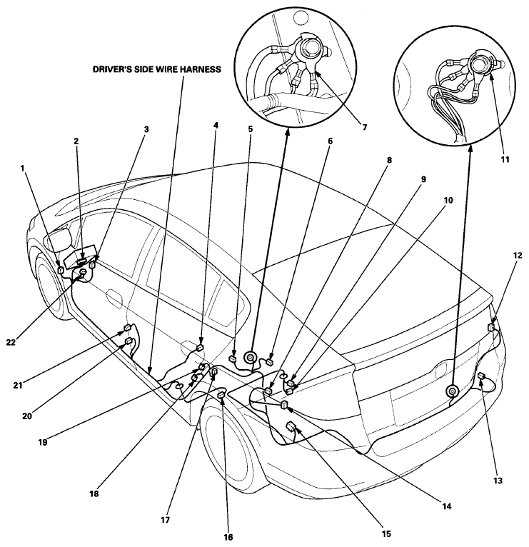
 DRIVER'S SIDE WIRE HARNESS
| Connector or Terminal |
Ref |
Cavities |
Location |
Connects to |
Notes |
| Cargo area light |
8 |
2 |
Left side of cargo area |
|
|
| Driver' s door switch |
20 |
1 |
Left B-pillar |
|
|
| EVAP canister vent shut valve |
9 |
2 |
Under floor |
|
|
| Fuel tank pressure sensor |
10 |
3 |
Under floor |
|
|
| IPU module fan |
13 |
4 |
Behind right side of cargo area |
|
|
| Left rear door switch |
19 |
1 |
Left C-pillar |
|
|
| Left taillight/brake light/back-up light/rear turn signal light/rear side marker light |
14 |
5 |
Behind left side of cargo area |
|
|
| Left side curtain airbag inflator |
6 |
2 |
Left C-pillar |
|
|
| Left side impact sensor (second) |
18 |
2 |
Left C-pillar |
|
|
| Noise reduction condenser |
17 |
2 |
Left C-pillar |
|
|
| Right taillight/brake light/back-up light/rear turn signal light/rear side marker light |
12 |
5 |
Behind right side of cargo area |
|
|
| Left rear wheel speed sensor |
16 |
2 |
Under floor |
|
|
| Under-dash fuse/relay box connector C (see
FUSE TO COMPONENTS INDEX
) |
2 |
49 |
Under left side of dash |
|
|
| C305 |
3 |
16 |
Under left side of dash |
Left engine compartment wire harness (see Left Engine Compartment Wire Harness (Dash branch)
) |
|
| C402 |
22 |
13 |
Under left side of dash |
Dashboard wire harness (see Dashboard Wire Harness (View of driver's side)
) |
|
| C501 |
4 |
4 |
Under floor |
Floor wire harness (see Floor Wire Harness (Right Branch)
) |
|
| C601 |
1 |
4 |
Under left side of dash |
Driver's door wire harness (see Driver's Door Wire Harness
) |
|
| C602 |
5 |
12 |
Left C-pillar |
Hatch subharness (see Hatch Subharness
) |
|
| C603 |
15 |
20 |
Behind left side of cargo area |
IPU wire harness (see IPU wire harness
) |
|
| C605 |
21 |
12 |
Left B-pillar |
Left rear door wire harness (see Left Rear Door Wire Harness
) |
|
| G701 |
11 |
|
Behind middle of cargo area |
Body ground, via driver's side wire harness |
|
| G702 |
7 |
|
Left C-pillar |
Body ground, via driver's side wire harness |
|
 Courtesy of AMERICAN HONDA MOTOR CO., INC.
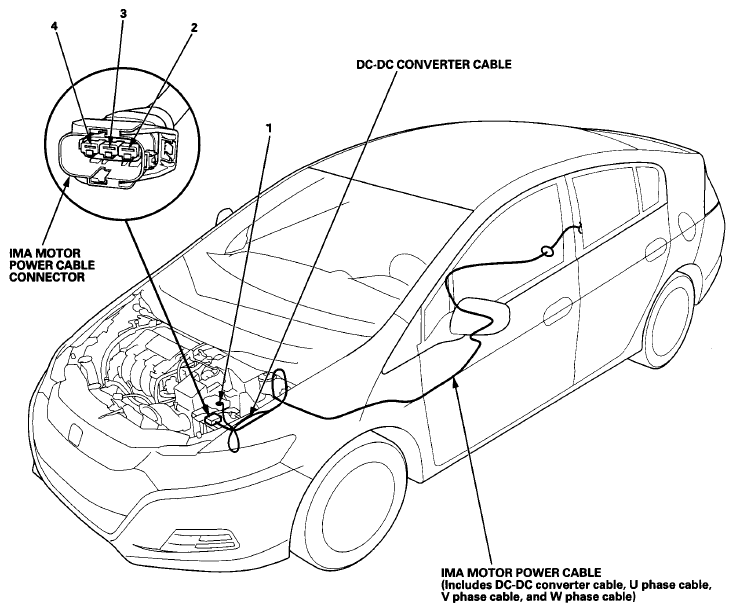
 IMA MOTOR POWER CABLE (ENGINE COMPARTMENT BRANCH)
| Connector or Terminal |
Ref |
Cavities |
Location |
Connects to |
Notes |
| T-2 |
1 |
|
Left side of engine compartment |
Battery terminal fuse box (see
CONNECTOR TO FUSE/RELAY BOX INDEX
) |
Terminal of DC-DC converter cable |
| T-14 |
4 |
|
Under air cleaner |
IMA motor |
Terminal of U phase cable |
| T-15 |
3 |
|
Under air cleaner |
IMA motor |
Terminal of V phase cable |
| T-16 |
2 |
|
Under air cleaner |
IMA motor |
Terminal of W phase cable |
 Courtesy of AMERICAN HONDA MOTOR CO., INC.
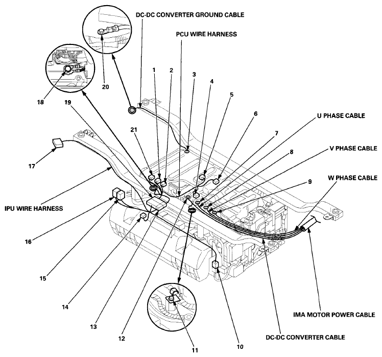
 IMA MOTOR POWER CABLE (CARGO AREA BRANCH)
| Connector or Terminal |
Ref |
Cavities |
Location |
Connects to |
Notes |
| T-10 |
12 |
|
Intelligent Power Unit |
DC-DC converter |
Terminal of DC-DC converter cable |
| T-11 |
7 |
|
Intelligent Power Unit |
Phase motor current sensor |
Terminal of U phase cable |
| T-12 |
8 |
|
Intelligent Power Unit |
Phase motor current sensor |
Terminal of V phase cable |
| T-13 |
9 |
|
Intelligent Power Unit |
Phase motor current sensor |
Terminal of W phase cable |
| G5 |
11 |
|
Intelligent Power Unit |
Body ground, via DC-DC converter cable |
|
IPU WIRE HARNESS
| Connector or Terminal |
Ref |
Cavities |
Location |
Connects to |
Notes |
| Junction board |
10 |
12 |
Intelligent Power Unit |
|
|
| Motor control module relay 1 |
15 |
4 |
In the IPU relay holder |
|
|
| Motor control module relay 2 |
16 |
4 |
In the IPU relay holder |
|
|
| C603 |
17 |
20 |
Intelligent Power Unit |
Driver's side wire harness (see Driver's Side Wire Harness
) |
|
| C701 |
13 |
4 |
Intelligent Power Unit |
PCU wire harness |
|
| C702 |
19 |
28 |
Intelligent Power Unit |
PCU wire harness |
|
| C703 (Junction connector) |
14 |
12 |
Intelligent Power Unit |
|
|
PCU WIRE HARNESS
| Connector or Terminal |
Ref |
Cavities |
Location |
Connects to |
Notes |
| Motor control module connector A |
21 |
31 |
Intelligent Power Unit |
|
|
| Motor control module connector B |
1 |
24 |
Intelligent Power Unit |
|
|
| Motor control module connector C |
2 |
22 |
Intelligent Power Unit |
|
|
| DC-DC converter |
5 |
4 |
Intelligent Power Unit |
|
|
| MPI module |
6 |
12 |
Intelligent Power Unit |
|
|
| Phase motor current sensor |
4 |
9 |
Intelligent Power Unit |
|
|
| C701 |
13 |
4 |
Intelligent Power Unit |
IPU wire harness |
|
| C702 |
19 |
28 |
Intelligent Power Unit |
IPU wire harness |
|
| G901 |
18 |
|
Intelligent Power Unit |
Body ground, via PCU wire harness |
|
DC-DC CONVERTER GROUND CABLE
| Connector or Terminal |
Ref |
Cavities |
Location |
Connects to |
Notes |
| T-17 |
3 |
|
Intelligent Power Unit |
DC-DC converter |
|
| G4 |
20 |
|
Intelligent Power Unit |
Body ground, via DC-DC converter ground cable |
|
 Courtesy of AMERICAN HONDA MOTOR CO., INC.
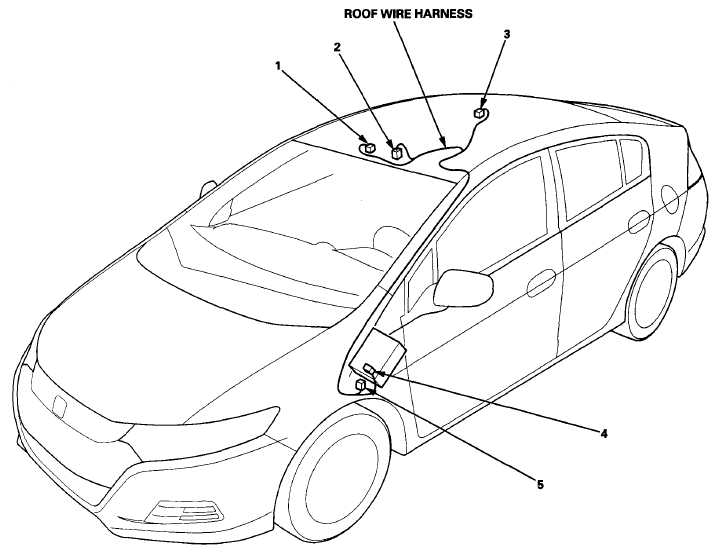
 ROOF WIRE HARNESS
| Connector or Terminal |
Ref |
Cavities |
Location |
Connects to |
Notes |
| Ceiling light |
3 |
3 |
Middle of roof |
|
|
| HFL-navigation microphone |
1 |
3 |
Front of roof |
|
|
| Individual map light |
2 |
3 |
Front of roof |
|
|
| Under-dash fuse/relay box connector G (see
FUSE TO COMPONENTS INDEX
) |
4 |
8 |
Under left side of dash |
|
|
| C401 |
5 |
4 |
Under left side of dash |
Dashboard wire harness (see Dashboard Wire Harness (View of driver's side)
) |
|
 Courtesy of AMERICAN HONDA MOTOR CO., INC.
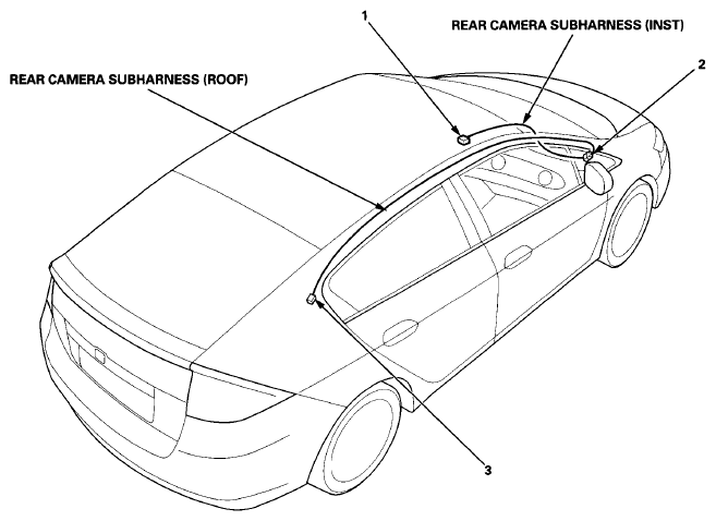
 REAR CAMERA SUBHARNESS (INST) (WITH NAVIGATION)
| Connector or Terminal |
Ref |
Cavities |
Location |
Connects to |
Notes |
| Audio-navigation unit connector C |
1 |
7 |
Middle of dash |
|
|
| C412 |
2 |
6 |
Under right side of dash |
Rear camera subharness (roof) |
|
REAR CAMERA SUBHARNESS (ROOF) (WITH NAVIGATION)
| Connector or Terminal |
Ref |
Cavities |
Location |
Connects to |
Notes |
| C412 |
2 |
6 |
Under right side of dash |
Rear camera subharness (inst) |
|
| C803 |
3 |
6 |
Right rear piller |
Rear window ground cable (see Rear Window Ground Cable ) |
|
 Courtesy of AMERICAN HONDA MOTOR CO., INC.
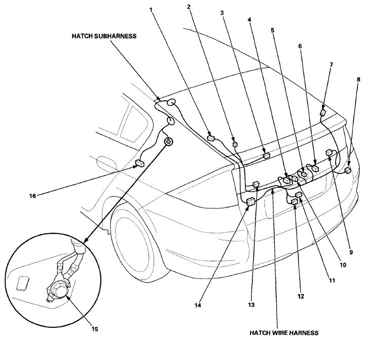
 HATCH SUBHARNESS
| Connector or Terminal |
Ref |
Cavities |
Location |
Connects to |
Notes |
| C602 |
16 |
12 |
Left C-pillar |
Driver's side wire harness (see Driver's Side Wire Harness
) |
|
| C801 |
14 |
12 |
Left side of hatch |
Hatch wire harness |
|
| G801 |
15 |
|
Left C-pillar |
Body ground, via hatch subharness |
|
HATCH WIRE HARNESS
| Connector or Terminal |
Ref |
Cavities |
Location |
Connects to |
Notes |
| Lower rear window defogger (-) |
9 |
1 |
Right side of hatch |
|
|
| Lower rear window defogger (+) |
13 |
1 |
Left side of hatch |
|
|
| Hatch latch switch |
11 |
2 |
Lower side of hatch |
|
|
| Hatch outer handle switch |
5 |
2 |
Middle of hatch |
|
|
| Hatch release actuator |
12 |
2 |
Lower side of hatch |
|
|
| High mount brake light |
3 |
2 |
Middle of hatch |
|
|
| Left license plate light |
4 |
2 |
Middle of hatch |
|
|
| Upper rear window defogger (-) |
7 |
1 |
Right side of hatch |
|
|
| Upper rear window defogger (+) |
1 |
1 |
Left side of hatch |
|
|
| Rear camera |
10 |
6 |
Middle of hatch |
|
With navigation |
| Rear window wiper motor |
2 |
4 |
Left side of hatch |
|
|
| Right license plate light |
6 |
2 |
Middle of hatch |
|
|
| C801 |
14 |
12 |
Left side of hatch |
Hatch subharness |
|
| C802 |
8 |
6 |
Right side of hatch |
Rear window ground cable (see Rear Window Ground Cable
) |
With navigation |
 Courtesy of AMERICAN HONDA MOTOR CO., INC.
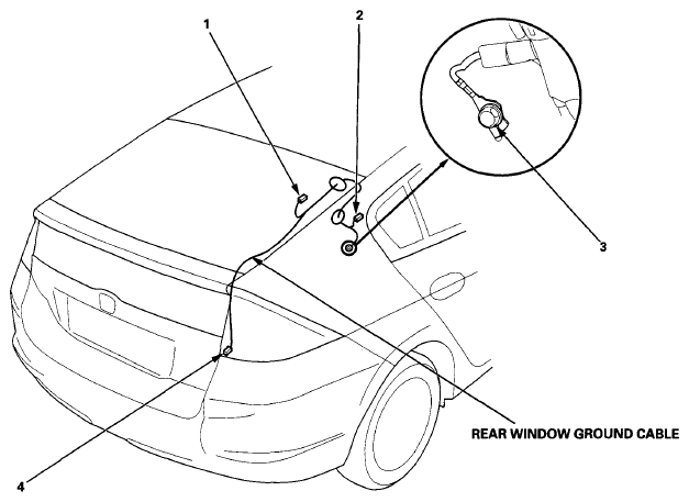
 REAR WINDOW GROUND CABLE
| Connector or Terminal |
Ref |
Cavities |
Location |
Connects to |
Notes |
| Rear window |
1 |
1 |
Right side of hatch |
|
|
| C802 |
4 |
6 |
Right side of hatch |
Hatch wire harness (see Hatch wire harness
) |
|
| C803 |
2 |
6 |
Right rear piller |
Rear camera subharness (roof) (see Rear Camera Subharness (Inst) (With navigation)
) |
With navigation |
| G851 |
3 |
|
Right rear piller |
Body ground, via rear window ground cable |
|
 Courtesy of AMERICAN HONDA MOTOR CO., INC.
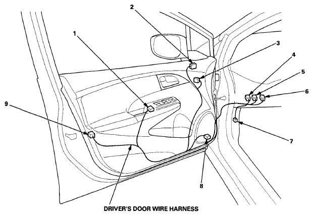
 DRIVER'S DOOR WIRE HARNESS
| Connector or Terminal |
Ref |
Cavities |
Location |
Connects to |
Notes |
| Driver's door key cylinder switch/lock knob switch/lock actuator |
9 |
10 |
Driver's door |
|
|
| Driver's power window motor |
3 |
6 |
Driver's door |
|
|
| Left front door speaker |
8 |
2 |
Driver's door |
|
|
| Left power mirror |
2 |
6 |
Driver's door |
|
Without side turn signal light |
| Left power mirror |
2 |
13 |
Driver's door |
|
With side turn signal light |
| Power window master switch |
1 |
22 |
Driver's door |
|
|
| Under-dash fuse/relay box connector E (see
FUSE TO COMPONENTS INDEX
) |
5 |
12 |
Under left side of dash |
|
|
| Under-dash fuse/relay box connector F (see
FUSE TO COMPONENTS INDEX
) |
4 |
6 |
Under left side of dash |
|
|
| C403 |
6 |
18 |
Under left side of dash |
Dashboard wire harness (see Dashboard Wire Harness (View of driver's side)
) |
|
| C601 |
7 |
4 |
Under left side of dash |
Driver's side wire harness (see Driver's Side Wire Harness
) |
|
 Courtesy of AMERICAN HONDA MOTOR CO., INC.
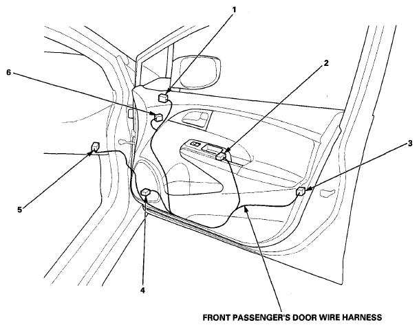
 FRONT PASSENGER'S DOOR WIRE HARNESS
| Connector or Terminal |
Ref |
Cavities |
Location |
Connects to |
Notes |
| Front passenger's power window motor |
6 |
2 |
Front passenger's door |
|
|
| Front passenger's power window switch |
2 |
8 |
Front passenger's door |
|
|
| Front passenger's door lock knob switch/lock actuator |
3 |
10 |
Front passenger's door |
|
|
| Right front door speaker |
4 |
2 |
Front passenger's door |
|
|
| Right power mirror |
1 |
6 |
Front passenger's door |
|
Without side turn signal light |
| Right power mirror |
1 |
13 |
Front passenger's door |
|
With side turn signal light |
| C411 |
5 |
18 |
Under right side of dash |
Dashboard wire harness (see Dashboard Wire Harness (View of passenger's side)
) |
|
 Courtesy of AMERICAN HONDA MOTOR CO., INC.
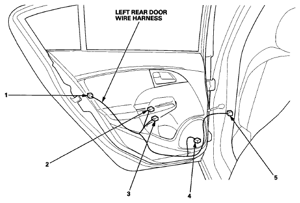
 LEFT REAR DOOR WIRE HARNESS
| Connector or Terminal |
Ref |
Cavities |
Location |
Connects to |
Notes |
| Left rear door lock knob switch/lock actuator |
1 |
10 |
Left rear door |
|
|
| Left rear door speaker |
4 |
2 |
Left rear door |
|
|
| Left rear power window motor |
3 |
2 |
Left rear door |
|
|
| Left rear power window switch |
2 |
8 |
Left rear door |
|
|
| C605 |
5 |
12 |
Left B-pillar |
Driver's side wire harness (see Driver's Side Wire Harness
) |
|
 Courtesy of AMERICAN HONDA MOTOR CO., INC.
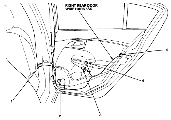
 RIGHT REAR DOOR WIRE HARNESS
| Connector or Terminal |
Ref |
Cavities |
Location |
Connects to |
Notes |
| Right rear door lock knob switch/lock actuator |
5 |
10 |
Right rear door |
|
|
| Right rear door speaker |
2 |
2 |
Right rear door |
|
|
| Right rear power window motor |
3 |
2 |
Right rear door |
|
|
| Right rear power window switch |
4 |
8 |
Right rear door |
|
|
| C502 |
1 |
12 |
Right B-pillar |
Floor wire harness (see Floor Wire Harness (Right Branch)
) |
|
 Courtesy of AMERICAN HONDA MOTOR CO., INC.
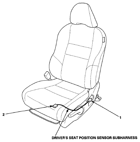
 DRIVER'S SEAT POSITION SENSOR SUBHARNESS
| Connector or Terminal |
Ref |
Cavities |
Location |
Connects to |
Notes |
| Driver's seat position sensor |
1 |
2 |
Driver's seat |
|
|
| C504 |
2 |
3 |
Under driver's seat |
Floor wire harness (see Floor Wire Harness (Left Branch)
) |
|
 Courtesy of AMERICAN HONDA MOTOR CO., INC.
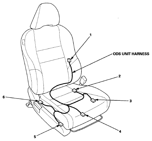
 ODS UNIT HARNESS
| Connector or Terminal |
Ref |
Cavities |
Location |
Connects to |
Notes |
| Front passenger's weight sensor (front inner) |
3 |
3 |
Front passenger's seat |
|
|
| Front passenger's weight sensor (front outer) |
5 |
3 |
Front passenger's seat |
|
|
| Front passenger's weight sensor (rear inner) |
2 |
3 |
Front passenger's seat |
|
|
| Front passenger's weight sensor (rear outer) |
6 |
3 |
Front passenger's seat |
|
|
| ODS unit |
1 |
18 |
Front passenger's seat |
|
|
| C503 |
4 |
4 |
Under front passenger's seat |
Floor wire harness (see Floor Wire Harness (Right Branch)
) |
|
 Courtesy of AMERICAN HONDA MOTOR CO., INC.
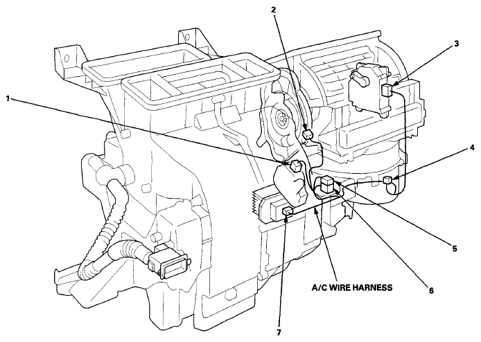
 A/C WIRE HARNESS
| Connector or Terminal |
Ref |
Cavities |
Location |
Connects to |
Notes |
| Air mix control motor |
1 |
7 |
Under middle of dash |
|
|
| Blower motor |
4 |
2 |
Under right side of dash |
|
|
| Mode control motor |
2 |
7 |
Under middle of dash |
|
|
| Power transistor |
7 |
4 |
Under middle of dash |
|
|
| Recirculation control motor |
3 |
7 |
Under middle of dash |
|
|
| C404 |
5 |
2 |
Under middle of dash |
A/C wire harness (see Dashboard Wire Harness (View of middle section) (With Navigation)
) |
|
| C404 |
5 |
2 |
Under middle of dash |
A/C wire harness (see Dashboard Wire Harness (View of middle section) (Without Navigation)
) |
|
| C405 |
6 |
16 |
Under middle of dash |
A/C wire harness (see Dashboard Wire Harness (View of middle section) (With Navigation)
) |
|
| C405 |
6 |
16 |
Under middle of dash |
A/C wire harness (see Dashboard Wire Harness (View of middle section) (Without Navigation)
) |
|
 Courtesy of AMERICAN HONDA MOTOR CO., INC.