Front Suspension
Knuckle/Hub/Wheel Bearing ReplacementKnuckle/Hub/Wheel Bearing:
Special Tools Required
^ Ball joint thread protector, 12 mm 07AAF-SDAA100
^ Hub dis/assembly tool 07GAF-SD40100
^ Ball joint remover, 32 mm 07MAC-SL0A102
^ Ball joint remover, 28 mm 07MAC-SL0A202
^ Ball joint thread protector, 14 mm 071AF-S3VA000
^ Attachment, 62 x 68 mm 07746-0010500
^ Driver 07749-0010000
^ Support base 07965-SD90100
Knuckle/Hub Replacement
1. Raise the front of the vehicle, and support it with safety stands in the proper locations.
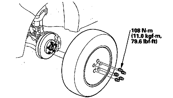
2. Remove the wheel nuts and front wheel.
3. Remove the brake hose bracket mounting bolt (A).
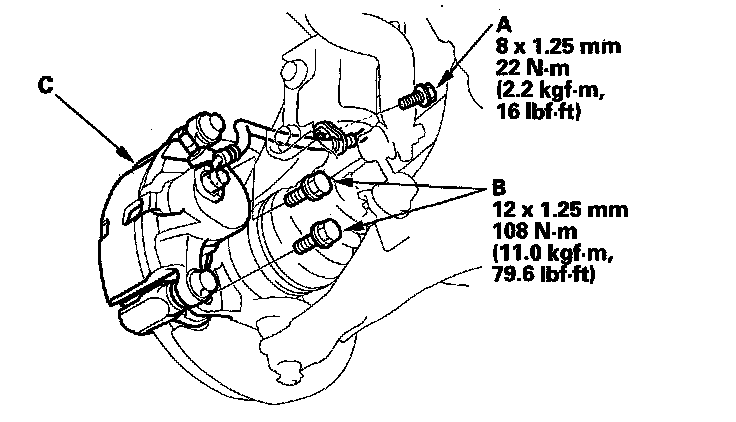
4. Remove the brake caliper bracket mounting bolts (B), then remove the caliper assembly (C) from the knuckle. To prevent damage to the caliper assembly or brake hose, use a short piece of wire to hang the caliper assembly from the undercarriage. Do not twist the brake hose excessively.
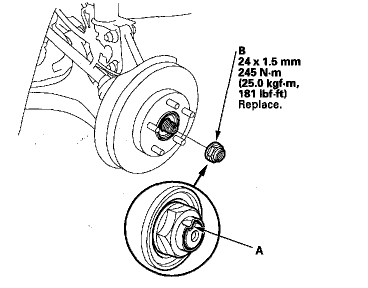
5. Raise the stake (A), then remove the spindle nut (B).
6. Remove the brake disc.
7. Check the front hub for damage and cracks.
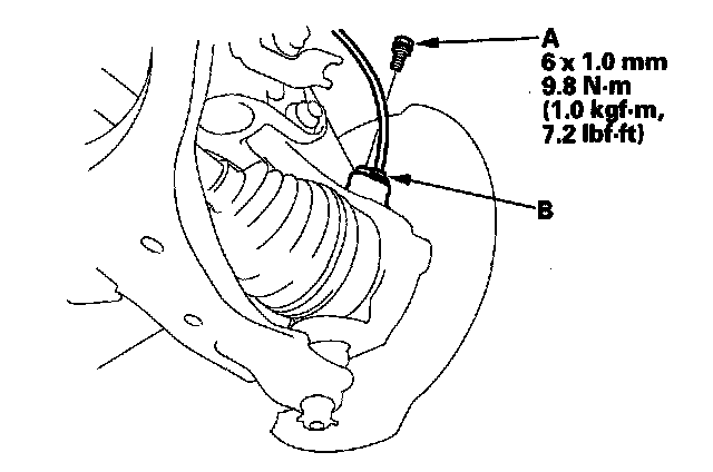
8. Remove the flange bolt (A) and wheel sensor (B) from the knuckle. Do not disconnect the wheel sensor connector.
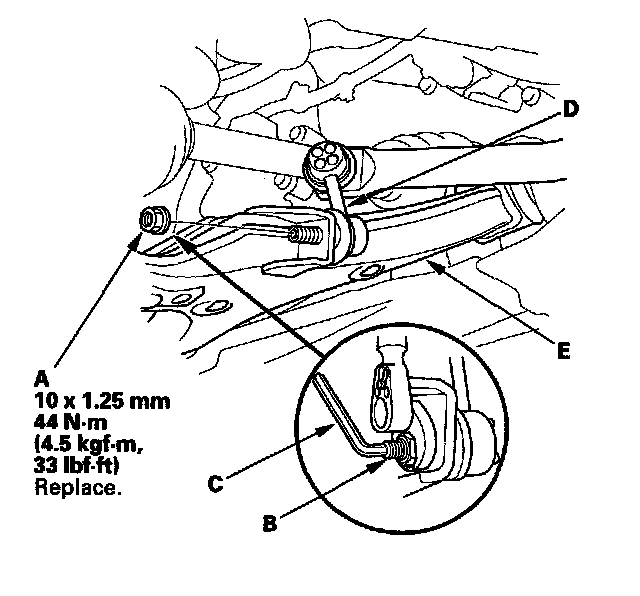
9. Remove the flange nut (A) while holding the joint pin (B) with a hex wrench (C), and disconnect the stabilizer link (D) from the lower arm (E).
NOTE: Use a new flange nut during reassembly.
10. Remove the lock pin (A) from the knuckle ball joint, then remove the castle nut (B).
NOTE: During installation, insert the lock pin as shown after tightening the new nut.
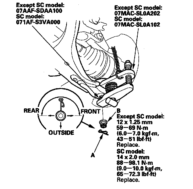
11. Disconnect the lower arm from the knuckle using the ball joint thread protector and ball joint remover.
12. Loosen the damper pinch bolts (A) while holding the nuts (B), and remove the bolts and the nuts.
NOTE: During installation, install new damper pinch bolts and new nuts.
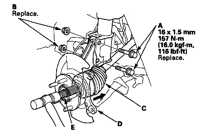
13. Remove the driveshaft outboard joint (C) from the knuckle (D) by tapping the driveshaft end (E) with a plastic hammer while drawing the hub outward, then remove the knuckle.
NOTE:
^ Do not pull the driveshaft end outward. The driveshaft inboard joint may come apart.
^ During installation, apply grease to the mating surfaces of the wheel bearing and the driveshaft outboard joint.
14. Install the knuckle/hub in the reverse order of removal, and note these items:
^ First install all the components, and lightly tighten the bolts and nuts, then raise the suspension with a floor jack to load it with the vehicle's weight before fully tightening to the specified torque values. Do not place the jack against the ball joint pin of the knuckle.
^ Be careful not to damage the ball joint boot when installing the knuckle.
^ Before connecting the knuckle ball joint to the lower arm, degrease the threaded section and tapered portion of the ball joint pin, the ball joint connecting hole, the threaded section, and mating surface of the castle nut.
^ Torque the castle nut to the lower torque specification, then tighten it only far enough to align the slot with the ball joint pin hole. Do not align the castle nut by loosening it.
^ Use a new spindle nut during reassembly.
^ Before installing the spindle nut, apply a small amount of engine oil to the seating surface of the nut. After tightening, use a drift to stake the spindle nut shoulder against the driveshaft.
^ Before installing the brake disc, clean the mating surfaces of the front hub and the inside of the brake disc.
^ Before installing the wheel, clean the mating surfaces of the brake disc and the inside of the wheel.
^ Check the wheel alignment, and adjust it if necessary.
Wheel Bearing Replacement
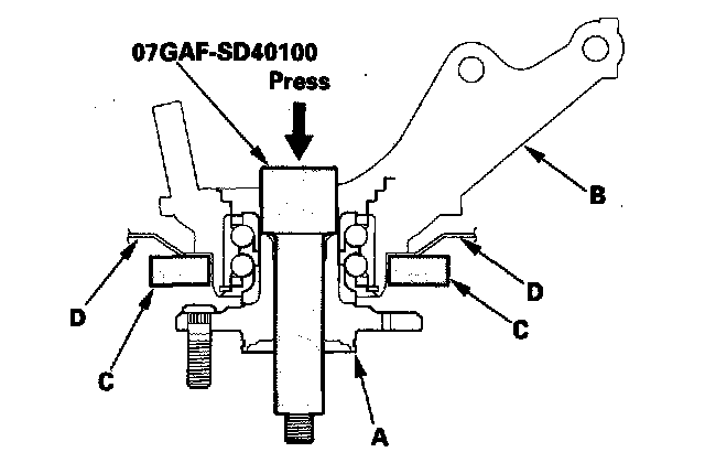
1. Separate the hub (A) from the knuckle (B) using the hub dis/assembly tool and a hydraulic press. Hold the knuckle with the attachment (C) of the hydraulic press or equivalent tool. Be careful not to deform the splash guard (D). Hold onto the hub to keep it from failing when pressed clear.
2. Press the wheel bearing inner race (A) out of the hub (B) using the hub dis/assembly tool, a commercially available bearing separator (C), and a press.

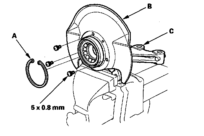
3. Remove the snap ring (A) and the splash guard (B) from the knuckle (C).
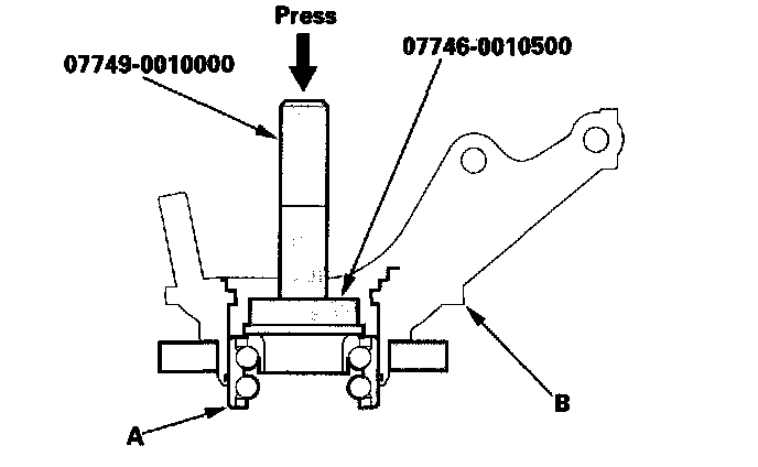
4. Press the wheel bearing (A) out of the knuckle (B) using the driver, the attachment, and a press.
5. Wash the knuckle and hub thoroughly in a high flash point solvent before reassembly.
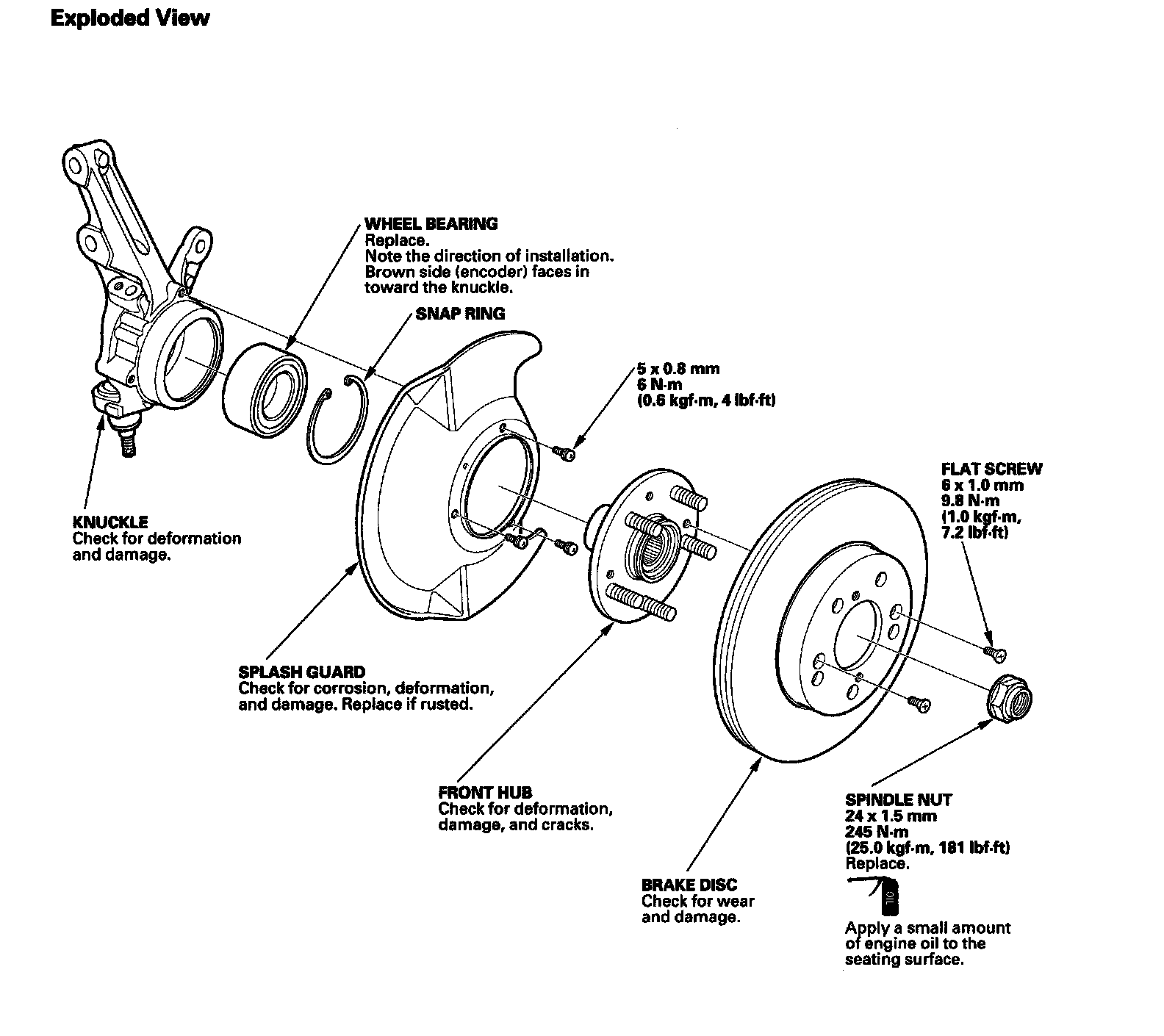
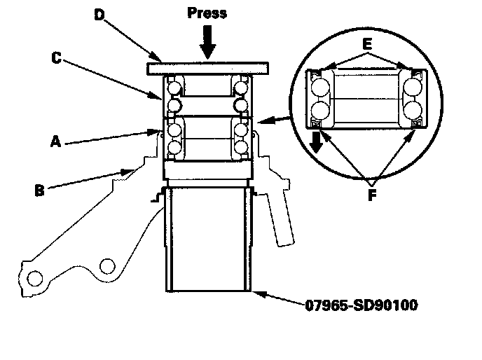
6. Press a new wheel bearing (A) into the knuckle (B) using the old bearing (C), a steel plate (D), the support base, and a press. Be careful not to damage the bearing seal (E).
NOTE:
^ Install the wheel bearing with the magnetic encoder (F) (brown color) toward the inside of the knuckle.
^ Remove any oil, grease, dust, metal debris, and other foreign material from the encoder surface.
^ Keep magnetic tools away from the encoder surface.
^ Be careful not to damage the encoder surface when you insert the wheel bearing.
7. Install the snap ring (A) securely in the knuckle (B).
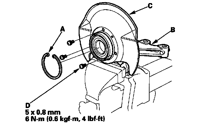
8. Install the splash guard (C), and tighten the screws (D) to the specified torque value.
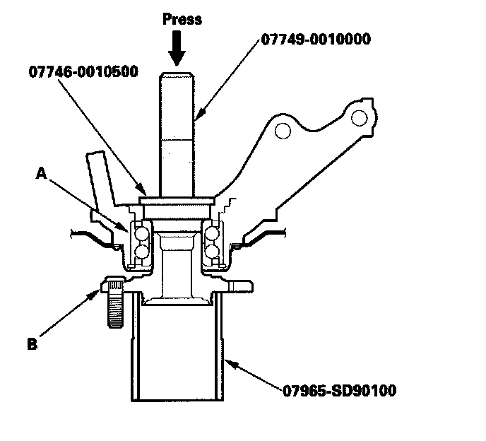
9. Press a wheel bearing (A) onto the hub (B) using the driver, the attachment, the support base, and a press.