Control Circuit Input Test
- Remove the gauge assembly (see Gauge Assembly Replacement
).
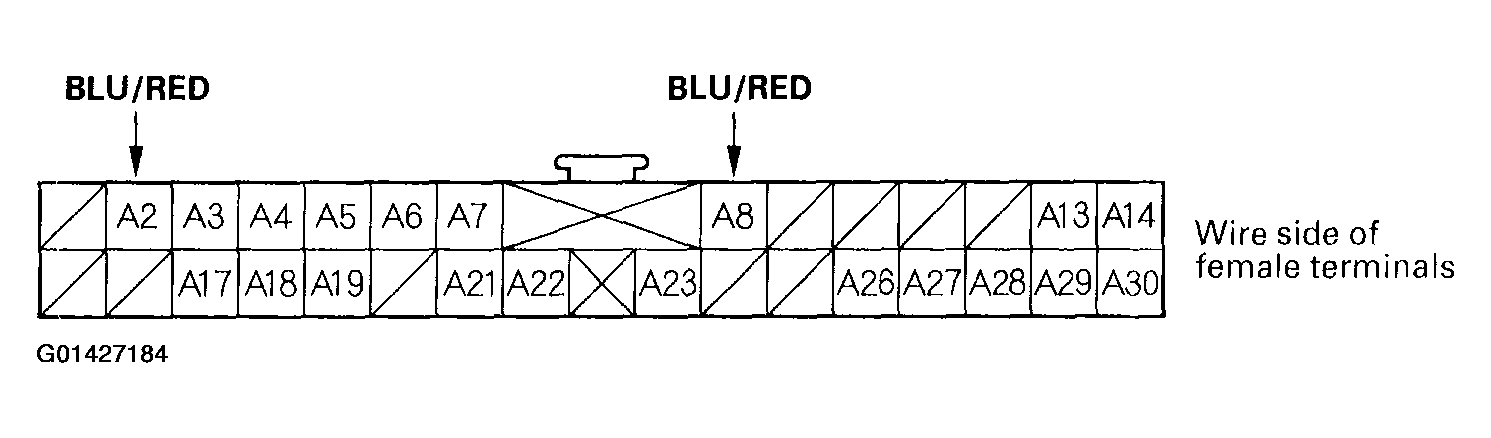
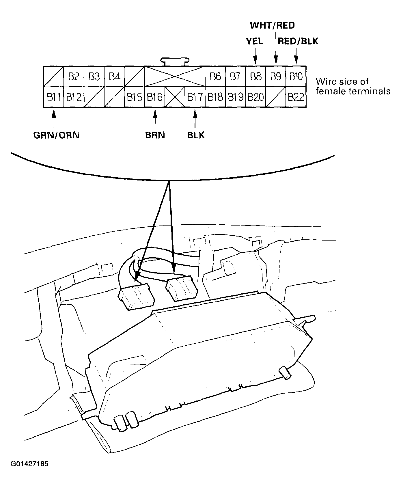
- Disconnect the gauge assembly 30P connector A and 22P connector B.
 Courtesy of AMERICAN HONDA MOTOR CO., INC.
 Courtesy of AMERICAN HONDA MOTOR CO., INC.
- Inspect the connector and socket terminals to be sure they are making good contact.
- If the terminals are bent, loose or corroded, repair them as necessary, and recheck the system.
- If the terminals look OK, go to step 4.
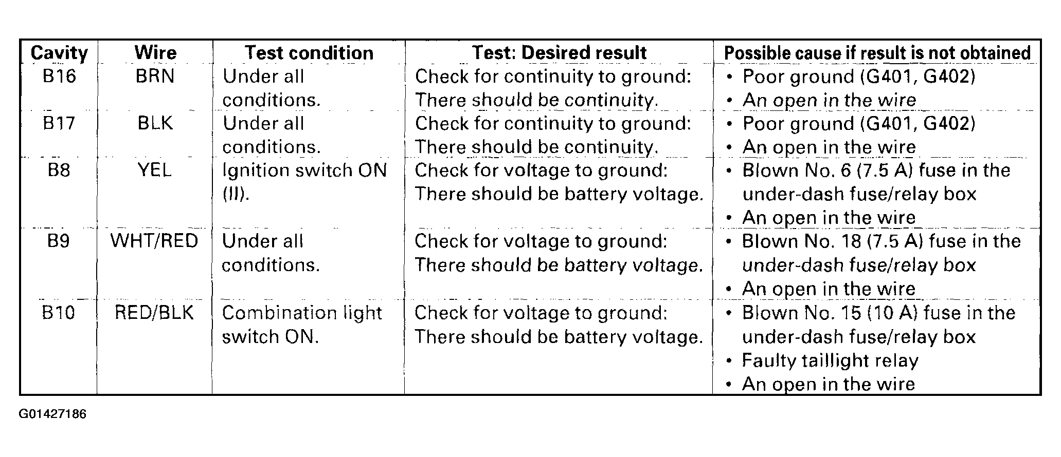
- With the connectors still disconnected, make these input tests at the connector. See Fig 3.
- If any test indicates a problem, find and correct the cause, then recheck the system.
- If all the input tests prove OK, go to step 5.
 Courtesy of AMERICAN HONDA MOTOR CO., INC.
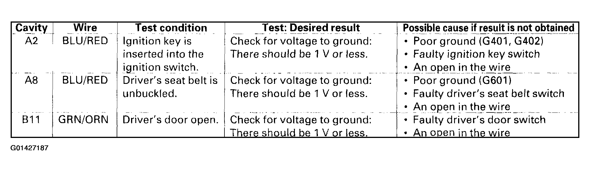
- Connect the connectors to the gauge assembly and make these input tests at the connector. See Fig 4.
- If any test indicates a problem, find and correct the cause, then recheck the system.
- If all the input tests prove OK, replace the printed circuit board in the gauge assembly.
 Courtesy of AMERICAN HONDA MOTOR CO., INC.