Dual Overhead Camshafts (DOHC): S2000
- Remove dipstick. Disconnect Positive Crankcase Ventilation (PCV) and breather hose. Remove ignition coil cover and ignition coils. Remove spark plugs and valve cover. Adjustment of exhaust and intake valves for each cylinder are done at same time. Rotate crankshaft to bring piston No. 1 to Top Dead Center (TDC) on compression stroke. Marks on timing chain pulley should be aligned with cylinder head surface. Marks on outer edges of camshaft pulleys should be pointing toward each other. See Fig 1. TDC groove (White mark) on crankshaft drive pulley should align with timing pointer.
- Measure clearance between valve stem and rocker arm. See VALVE CLEARANCE ADJUSTMENT SPECIFICATIONS (COLD) table. See Fig 2. Adjust valve clearances to specification if necessary. Loosen valve adjuster lock nuts, located under camshaft, and turn adjusting screw for each valve on cylinder No. 1. Go to next step.
- Tighten valve adjuster lock nuts to 14 ft. lbs. (19 N.m). Check valve clearance after tightening lock nut. Readjust valve clearance, if necessary.
- Rotate crankshaft clockwise 180 degrees (camshaft pulleys rotate counterclockwise 90 degrees). Ensure mark on intake camshaft pulley is pointing down, mark on exhaust camshaft pulley is pointing up, and cylinder No. 3 is at TDC. Adjust valves on cylinder No. 3. Repeat step 3 and go to next step.
- Rotate crankshaft clockwise 180 degrees (camshaft pulleys rotate counterclockwise 90 degrees). Ensure mark on intake camshaft pulley and mark on exhaust camshaft pulley are pointing away from each other and cylinder No. 4 is at TDC. Adjust valves on cylinder No. 4. Repeat step 3 and go to next step.
- Rotate crankshaft clockwise 180 degrees (camshaft pulleys rotates counterclockwise 90 degrees). Ensure mark on intake camshaft pulley is pointing up and mark on exhaust camshaft pulley is pointing down and cylinder No. 2 is at TDC. Adjust valves on cylinder No. 2. Repeat step 3 and go to next step.
- After adjusting valve clearances, retighten crankshaft pulley bolt to 181 ft. lbs. (245 N.m). To complete valve adjusting procedure, reverse removal procedures. Ensure valve covers mating surfaces are clean. Ensure spark plug seals are not damaged. Tighten valve cover sequentially in 2-3 passes to 106 INCH lbs. (12 N.m). See Fig 3.
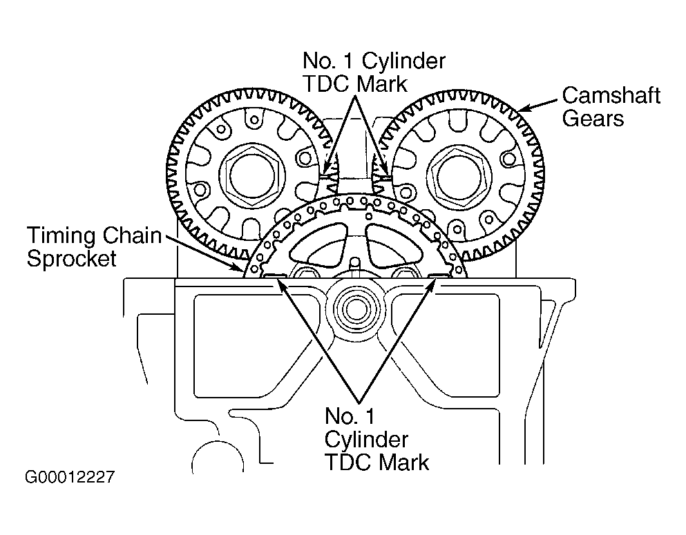 Courtesy of AMERICAN HONDA MOTOR CO., INC.
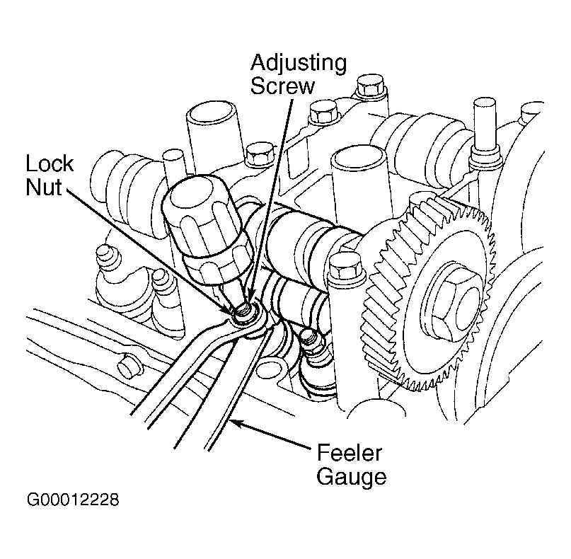 Courtesy of AMERICAN HONDA MOTOR CO., INC.
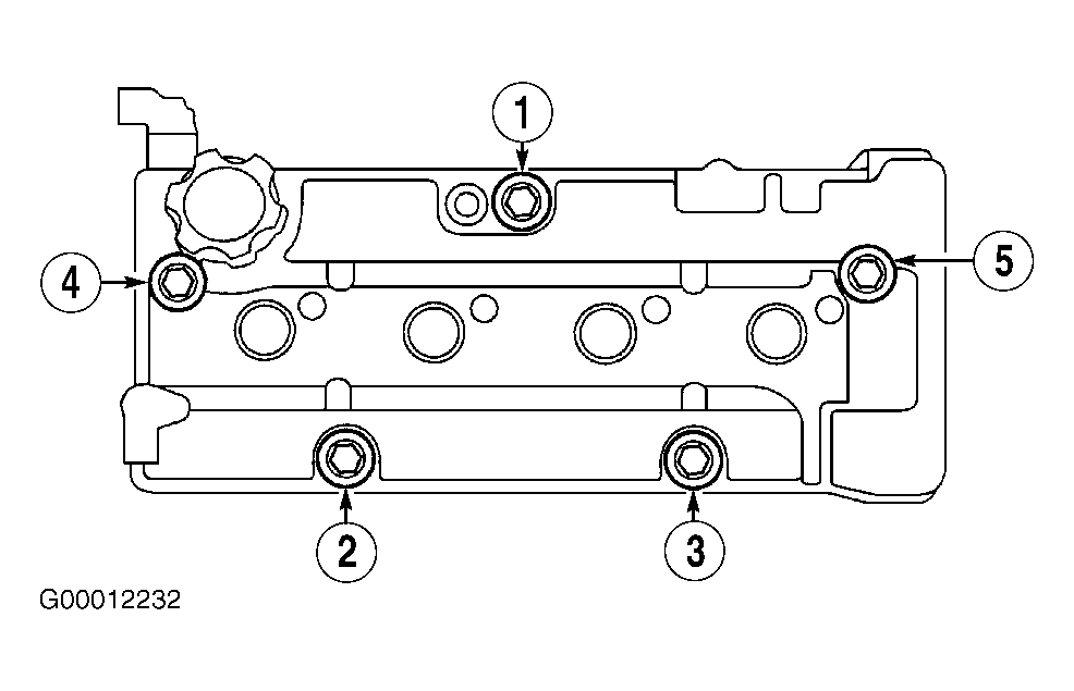 Courtesy of AMERICAN HONDA MOTOR CO., INC.