DTC 51, 52, 53: Pump Motor
- If ABS indicator light says on with ignition switch in ON position and DTC 51-53 is set, go to next step.
- Check fuse No. 63 (7.5-amp), located in underhood ABS fuse/relay box. If problem does not exist, install fuse and go to next step. If problem exists, replace fuse. Using jumper wire, momentarily ground ABS control unit connector "A" terminal No. 19 (Yellow/Red wire). See Figure
. If fuse No. 63 blows, repair short to ground in motor check circuit between fuse No. 63 and ABS control unit.
- Check fuse No. 61 (40-amp), located in underhood ABS fuse/relay box. If problem does not exist, go to next step. If problem exists, replace fuse. Using jumper wire, momentarily ground ABS control unit connector "A" terminal No. 19 (Yellow/Red wire). See Figure
. If fuse No. 61 blows, repair short to ground in White wire between underhood ABS fuse/relay box and pump motor.
- Check pump motor relay. See PUMP MOTOR RELAY TEST
under COMPONENT TESTS. If problem exists, replace pump motor relay. If problem does not exist, go to next step.
- Turn ignition on. If pump motor does not operate, go to next step. If pump motor operates, remove pump motor relay. If pump motor operates, repair short to power in White wire between underhood ABS fuse/relay box and pump motor. If pump motor does not operate, check for loose ABS control unit connectors. If problem exists, repair connector(s) as necessary. If problem does not exist, replace ABS control unit and retest system.
- Remove pump motor relay. Turn ignition on. Using fused jumper wire, momentarily jumper pump motor relay connector terminals No. 4 and 5. See Fig 1
. If pump motor operates, go to step 9
. If pump motor does not operate, go to next step.
- Turn ignition off. Disconnect pump motor 2-pin connector. Turn ignition on. Connect fused jumper wire between pump motor relay connector terminals No. 4 and 5. Measure voltage between ground and pump motor connector terminal No. 1 (White wire). If battery voltage exists, go to next step. If battery voltage does not exist, repair open in White wire between underhood ABS fuse/relay box and pump motor.
- Connect jumper wire between battery negative terminal and pump motor connector terminal No. 2 (Brown wire). Momentarily connect fused jumper wire between battery positive terminal and pump motor connector terminal No. 1 (Red wire). If pump motor does not operate, replace modulator unit. If pump motor operates, repair open in Black wire between pump motor and ground. On Civic, ground is located at rear of right front strut tower. On CR-V, ground is located at right rear of engine compartment near underhood fuse/relay box.
- Turn ignition off. Disconnect ABS control unit 22-pin connector "A". Check for continuity between ground and ABS control unit connector "A" terminal No. 19 (Yellow/Red wire). See Figure
. If continuity does not exist, go to next step. If continuity exists, repair short to ground in Yellow/Red wire between underhood ABS fuse/relay box and ABS control unit.
- Turn ignition off. Reconnect ABS control unit connector "A". Connect fused jumper wire or SCS Service Connector (07PAZ-0010100) between service check connector terminals. See Figure
or Figure
. Turn ignition on. Measure voltage between ground and pump motor relay connector terminal No. 1 (Green/White wire). See Fig 1
. If about 3 volts exist, go to next step. If about 3 volts do not exist, repair open in Green/White wire between underhood ABS fuse/relay box and ABS control unit 26-pin connector "B".
- Measure voltage between ground and ABS control unit connector "A" terminal No. 19 (Yellow/Red wire) by backprobing. If about 3 volts exist, go to next step. If about 3 volts do not exist, repair open in Yellow/Red wire between ABS control unit connector "A" and underhood ABS fuse/relay box.
- Turn ignition off. Disconnect fused jumper wire or SCS Service Connector (07PAZ-0010100) from service check connector. Turn ignition on. Momentarily jumper pump motor relay connector terminals No. 4 and 5 and measure voltage between ground and ABS control unit connector "A" terminal No. 17 (Brown/Yellow wire). See Figure
and Fig 1
. If battery voltage exists, go to next step. If battery voltage does not exist, repair open in Brown/Yellow wire between ABS control unit connector "A" and underhood ABS fuse/relay box.
- Check for loose ABS control unit connectors. If problem exists, repair connector(s). If problem does not exist, replace ABS control unit and retest system.
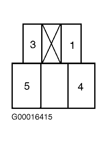 Courtesy of AMERICAN HONDA MOTOR CO., INC.