- Install gear spring, sub-gear and wave washer. See Figure
. Align pin on gear with gear spring ends. Install snap ring. Install pins "A" and "B" in sub-gear. See Figure
. Using screwdriver, rotate sub-gear clockwise. Install service bolt and remove pins.
CAUTION:
Keep camshaft level during installation, or camshaft binding and breakage may occur.
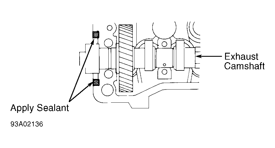
- To install exhaust camshaft, lubricate thrust area of camshaft with multipurpose grease. Install exhaust camshaft so knock pin is in 4 o'clock position. This angle allows No. 1 and No. 3 cylinder cam lobes to push on valve lifters evenly. Apply RTV sealer (1052917) to No 1 bearing cap. See Fig 1
. Install exhaust camshaft bearing caps on cylinder head.
CAUTION:
Ensure arrow on camshaft bearing cap points toward timing belt end of engine. Install caps so numbers are in order.
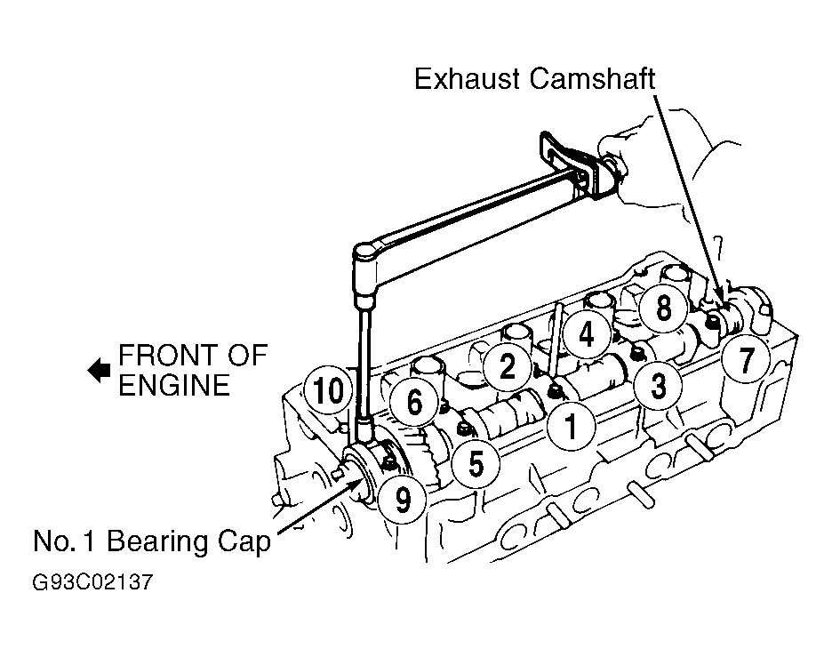
- Tighten bolts on exhaust camshaft bearing caps evenly in sequence. See Fig 2
. Tighten bolts to specification. See TORQUE SPECIFICATIONS
.
- Apply multipurpose grease on camshaft oil seal. Using Seal Installer (J-35403), install seal on exhaust camshaft.
 Courtesy of TOYOTA MOTOR SALES, U.S.A., INC.
 Courtesy of TOYOTA MOTOR SALES, U.S.A., INC.
CAUTION:
DO NOT confuse TDC marks with camshaft aligning marks. During camshaft installation, ensure installing marks, not TDC marks, are aligned.
- To install intake camshaft, rotate exhaust camshaft so knock pin is at approximately 10 o'clock position. See Fig 3
. Lubricate thrust area of camshaft with multipurpose grease. Install intake camshaft so installing marks on camshaft gears are aligned.
- Install all camshaft bearing caps, except No. 1, on cylinder head. Tighten both bolts on each camshaft bearing cap in sequence. See Fig 2
. Tighten bolts to specification. See TORQUE SPECIFICATIONS
.
CAUTION:
Ensure arrow on camshaft bearing cap points toward timing belt end of engine. Install bearing caps so numbers are in order.
- Remove bolt from service bolt hole. Install No. 1 bearing cap. If No. 1 camshaft bearing cap does not fit properly, push camshaft gear backward while installing camshaft bearing cap. Tighten bolts to specification. See TORQUE SPECIFICATIONS
. Rotate exhaust camshaft clockwise so knock pin is at 12 o'clock position.
- Ensure TDC marks are together and at cylinder head surface. See Fig 3
. The installing marks should be at 12 o'clock position.
CAUTION:
Check valve clearance if cylinder head or camshaft components were serviced or changed. See VALVE CLEARANCE ADJUSTMENT
under ADJUSTMENTS.
- To install remaining components, reverse removal procedure. Before installing valve cover, apply Sealant (1052751) at valve cover-to-camshaft bearing cap surfaces.