Crankshaft & Main Bearings
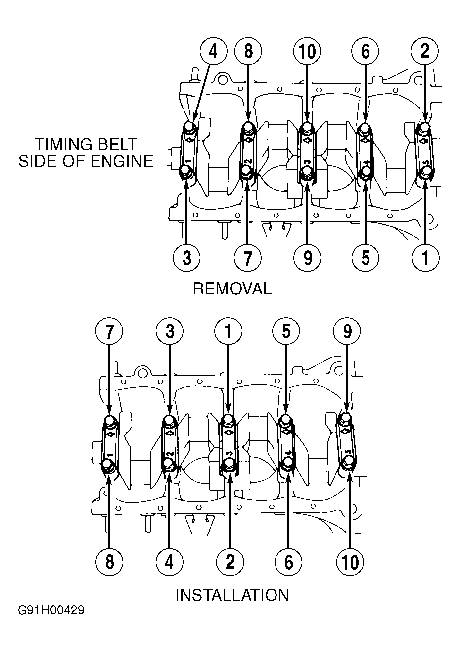
- Ensure main bearing caps are numbered for location, and arrow on cap points toward timing belt end of crankshaft. Remove main bearing cap bolts in proper sequence. See Fig 1
.
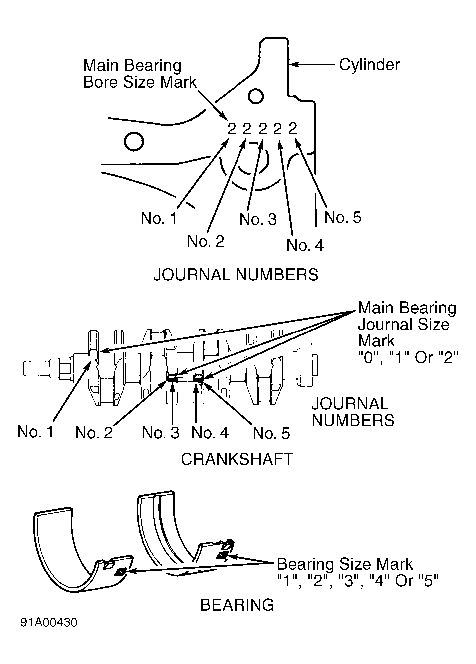
- Cylinder block main bearing bore size is indicated by a size mark number, "1", "2" or "3", stamped on cylinder block. Refer to Fig 2
. Main bearing journal size is indicated by a size mark number, "0", "1" or "2", located near crankshaft counterweight.
 Courtesy of GENERAL MOTORS CORP.
 Courtesy of TOYOTA MOTOR SALES, U.S.A., INC.
- Measure main bearing clearance using Plastigage method. Main bearing clearance should be .0006-.0013" (.015-.033 mm). Maximum wear tolerance is .004 (.10 mm). If bearing clearance is excessive, measure crankshaft main bearing journals. Measure journals at each end of journal and 90 degrees from first readings. Grind crankshaft to .0098" (.25mm) undersize or replace crankshaft if journal minimum diameter, taper or out-of-round are not within specification.
- When replacing worn bearings on a crankshaft that is within original specification, use size markings on bearings to identify replacement bearing. If bearing size mark on original bearing cannot be obtained, use number on cylinder block (main bearing bore size mark) and number on crankshaft (main bearing journal size mark) to determine bearing number. See MAIN BEARING SELECTION table.
MAIN BEARING SELECTION
| Main Bearing Bore Size Mark |
Main Bearing Journal Size Mark |
Bearing Size Mark |
| "1" |
"0" |
"1" |
| "1" |
"1" |
"2" |
| "1" |
"2" |
"3" |
| "2" |
"0" |
"2" |
| "2" |
"1" |
"3" |
| "2" |
"2" |
"4" |
| "3" |
"0" |
"3" |
| "3" |
"1" |
"4" |
| "3" |
"2" |
"5" |
- When installing main bearing caps, ensure arrow on cap points toward timing belt end of crankshaft. Tighten bolts in sequence. See Fig 1
.
- Tighten bolts to specification. See TORQUE SPECIFICATIONS TABLE at the end of this article. Ensure crankshaft end play is within specification. See CRANKSHAFT, MAIN & CONNECTING ROD BEARINGS table under ENGINE SPECIFICATIONS.