Transaxle Reassembly
NOTE:
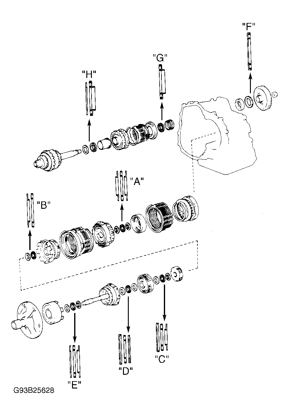
Coat all oil seal rings, discs, plates, rotating parts and sliding surfaces with ATF prior to reassembly. Use petroleum jelly to hold parts in place. Discs should be soaked in ATF for at least 15 minutes prior to installation. For bearing race and thrust bearing specifications, see refer to the BEARING RACE & THRUST BEARING SPECIFICATIONS . For bearing race and thrust bearing locations, see Fig 3.
- Using Bearing Installer (09351-32140) and press, install bearing in transaxle housing. Install bearing stopper. Install oil tube apply cover and gasket. Install oil tubes. Install oil tube clamps. Using Bearing Installer (09351-32090), install bearing in transaxle case. Install underdrive brake accumulator piston and spring. See Figure.
- Install oil gallery cover and gasket. Tighten bolts to 89 INCH lbs. (10 N.m). Apply Seal Packing 3 Bond (1324) to screws for oil gallery cover. Install screws and tighten.
- Install manual shaft, washer, spacer and lever. Install retaining spring. Ensure washer is located between retaining spring and transaxle case. Install pin. Stake spacer in proper position. See Figure. Install cam guide bracket.
- Install parking lock rod in guide bracket. Install parking lock sleeve with raised portion up. Install stopper plate on raised portion of lock sleeve. Install guide sleeve and spring. Install parking lock pawl, pawl shaft and shaft clamp. See Figure.
- Install NEW "O" rings on 1st and reverse brake piston. Lubricate "O" rings with ATF. Using Piston Spring Compressor (09351-32040), press 1st and reverse brake piston into transaxle case. Install piston return spring and snap ring. Avoid bending spring retainer by overtightening bolt. Ensure snap ring is fully seated and centered by 3 lugs on spring retainer. Ensure end gap of snap ring is not aligned with spring retainer claw.
- Install underdrive brake piston "O" rings. Coat "O" rings with ATF. Install piston in transaxle case with cup side upward. Use care not to damage "O" rings. Install brake piston return spring. Install 3 plates and 3 discs. Start with plate and alternate with disc ending with disc. Install flange with flat end down.
- Using Spring Compressor (09351-32070), compress return spring. Install snap ring. Ensure snap ring end gap is not aligned with cutout. Using compressed air, confirm underdrive brake piston moves smoothly. See Figure. Install oil seal rings to transaxle case.
- Install underdrive one-way clutch assembly. Install anti-rattle clip. Align clutch disc tabs and install underdrive clutch assembly. Check operation of underdrive one-way clutch. Clutch should turn freely counterclockwise and lock clockwise.
- Measure clutch assembly height from sleeve to inner race. Height should be .681-.717" (17.29-18.21 mm). Check underdrive clutch piston stroke. Position dial indicator stem on underdrive clutch assembly. Apply compressed air to oil passage in transaxle case. See Figure.
- For A-240E and A-241L transaxles, piston stroke should be .058-074" (1.47-1.89 mm). For A-240L and A-244E transaxles, piston stroke should be .059-.073" (1.50-1.86 mm). For A-241E and A-243L transaxles, piston stroke should be .048-.061" (1.21-1.55 mm). If piston stroke is less than specification, parts may be installed incorrectly. If parts are installed correctly, flange may be incorrect size.
- Flange is available in thicknesses of .080" (2.04 mm) and .094" (2.40 mm) for A-240E, A-240L, A-241L and A-244E. Flange is available in thicknesses of .091" (2.30 mm), .098" (2.50 mm) and .106" (2.70 mm) for A-241E and A-243L transaxle. Install thrust bearing "G". See Fig 3. Install sun gear in transaxle case.
- Align clutch disc tabs in underdrive clutch. Install countershaft assembly. Check countershaft height. Using calipers, measure distance from tip of countershaft to bolt seat of clutch support. Countershaft height should be 1.311-1.398" (33.30-35.50 mm).
- Install thrust bearing "F". See Fig 3. Using Installer (09223-32040), install counterdriven gear. Install NEW lock nut. Using holder and adapter, tighten lock nut to 116 ft. lbs. (157 N.m) on A-240L transaxle, and 130-159 ft. lbs. (177-216 N.m) for all other transaxles. Using a dial indicator, measure countershaft end play. End play should be .009-.035" (.23-.89 mm). Stake lock nut. Install snap ring in transaxle case.
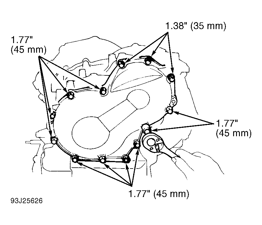
- Install intermediate shaft. Apply Loctite (518) to rear cover sealing areas. Install transaxle rear cover and bolts. Ensure bolts are installed in correct locations. See Fig 1. Tighten bolts to 21 ft. lbs. (29 N.m). Install apply gaskets in transaxle case. Install thrust washer and governor driven gear. See Figure. Ensure intermediate shaft rotates smoothly.
 Courtesy of © TOYOTA, LICENSE AGREEMENT TMS1002
- Install 1st and reverse brake components in transaxle case. Install inner flange with flat end facing upward. Install discs and plates. Start with disc, alternate with plate, ending with disc. Install outer flange with flat area facing inward. Install snap ring in groove. Ensure end gap does not align with transaxle case cutout.
- Check 1st and reverse brake operation. Apply light air pressure to oil passage. See Figure. Ensure piston moves smoothly. Install thrust bearing and races "A" in rear planetary ring gear. See Fig 3. Align disc tabs. Install rear planetary ring gear in transaxle case. Install thrust washer on rear planetary gear. Ensure tabs align with grooves of gear.
- Align spline of planetary gear with tabs of 1st and reverse brake discs. Install rear planetary gear into 1st and reverse brake. Ensure inner surface of rear planetary gear is below upper surface of flange. Install No. 2 one-way clutch with shiny side upward. Rotate planetary gear clockwise while installing No. 2 one-way clutch.
- Check No. 2 one-way clutch operation. Planetary gear should rotate clockwise and lock counterclockwise. Install thrust washer on planetary gear. Install snap ring. Ensure end gap of snap ring is not aligned with case cutouts.
- Install 2nd coast brake band guide with tip contacting transaxle case. Install 2nd brake flange with flat end facing upward. Install 3 discs and 3 plates, starting with disc, alternating with plate and ending with plate. Install piston return spring assembly with springs over case protrusions. Align 2nd brake drum groove with bolt in transaxle case.
- Install 2nd brake drum. Install snap ring in groove while compressing piston return springs with hammer handles. Ensure end gap of snap ring is not aligned with transaxle case cutouts. Install 2nd brake drum gasket in center oil passage until it contacts 2nd brake drum. Apply compressed air into 2nd brake oil passage in transaxle case. Ensure 2nd brake piston operates smoothly. See Figure.
- Align 2nd brake disc tabs. Install No. 1 one-way clutch and 2nd brake hub. Check distance between surface of 2nd brake hub and rear planetary gear. Distance should be approximately .20" (5.0 mm). Install thrust washer on sun gear input drum. Install sun gear and sun gear input drum. Rotate sun gear clockwise while installing gear into one-way clutch.
- Install thrust bearing and race "B" on front planetary gear. See Fig 3. Install planetary gear. Install thrust bearing and race "C" on front planetary ring gear. See Fig 3. Install front planetary ring gear. Install intermediate shaft oil seal ring.
- If components installed in transaxle case are correctly installed, end of ring gear flange bushing will be even or slightly lower than intermediate shaft shoulder. Install thrust bearing and races "D" on tip of ring gear flange. Install 2nd coast brake band into transaxle case. Install pin through oil pump mounting bolt hole.
- Install thrust bearing and race "E" on forward clutch drum. See Fig 3. Install clutch drum thrust washer on direct clutch drum with oil groove facing upward. Align clutch disc tabs. Install direct clutch into forward clutch. If tabs are aligned with hub correctly, end of direct clutch drum bushing will be flush with surfaces of forward clutch.
- Rotate forward clutch to mesh with front planetary gear and discs. Install direct clutch and forward clutch into transaxle case. Install differential. Apply Loctite (518) to transaxle housing. Install transaxle housing. Install mounting bolts in original locations. See Figure. Tighten bolts to 21 ft. lbs. (29 N.m). Check differential side bearing preload. See DIFFERENTIAL under COMPONENT DISASSEMBLY & REASSEMBLY.
- Install race on stator shaft. Install "O" ring on oil pump. Install oil pump. Hold input shaft and tightly press oil pump body to slide oil seal rings on stator shaft through direct clutch drum. Install and tighten bolts to 18 ft. lbs. (25 N.m).
NOTE:
DO NOT
apply excessive pressure on oil pump. Seal rings will stick to direct clutch drum if excessive pressure is used.
- Ensure input shaft rotates smoothly. Using a dial indicator, measure input shaft end play. End play should be .012-.035" (.30-.90 mm). Replace oil pump race if end play is incorrect. Oil pump races are available in thicknesses of .031" (.80 mm) and .055" (1.40 mm).
- Install spring, 2nd coast brake piston and cover into bore. Install snap ring. Ensure front end of piston rod contacts center of 2nd brake band depression. Measure 2nd coast brake piston stroke by applying compressed air to oil passage in transaxle case. See Figure.
- Piston stroke should be .059-.118" (1.50-3.00 mm). Replace piston rod with different length rod if not within specification. Piston rods are available in lengths of 2.811" (71.39 mm) and 2.870" (72.89 mm).
- Recheck piston stroke after changing piston rod. If stroke still exceeds specification, replace 2nd coast brake band. Coat accumulator piston "O" rings with ATF. Install "O" rings on accumulator pistons. Measure spring free length and replace as necessary.
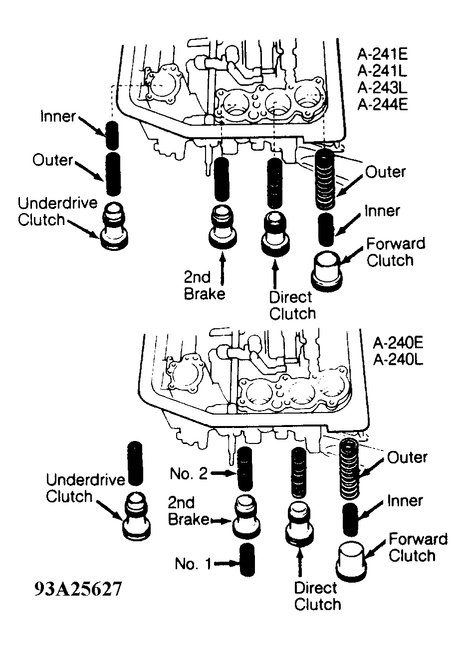
- See ACCUMULATOR SPRING SPECIFICATIONS . Install pistons and springs in transaxle case. See Fig 2. Install accumulator cover and NEW gasket. Tighten bolts to 89 INCH lbs. (10 N.m).
ACCUMULATOR SPRING SPECIFICATIONS
| Application |
Free Length: In. (mm) |
| A-240E |
| Direct Clutch |
2.500 (63.50) |
| Forward Clutch - Inner Spring |
1.673 (42.50) |
| Forward Clutch - Outer Spring |
3.063 (77.80) |
| Underdrive Clutch |
2.420 (61.47) |
| 2nd Brake - No. 1 |
1.385 (35.18) |
| 2nd Brake - No. 2 |
2.232 (56.68) |
| A-240L |
| Direct Clutch |
2.551 (64.80) |
| Forward Clutch - Inner Spring |
1.673 (42.50) |
| Forward Clutch - Outer Spring |
3.063 (77.80) |
| Underdrive Clutch |
2.548 (64.72) |
| 2nd Brake - No. 1 |
1.385 (35.18) |
| 2nd Brake - No. 2 |
2.232 (56.68) |
| A-241E |
| Direct Clutch |
2.462 (62.54) |
| Forward Clutch - Inner Spring |
1.614 (41.00) |
| Forward Clutch - Outer Spring |
2.917 (74.10) |
| Underdrive Clutch - Inner Spring |
1.890 (48.00) |
| Underdrive Clutch - Outer Spring |
2.570 (65.20) |
| 2nd Brake |
2.539 (64.50) |
| A-241L |
| Direct Clutch |
2.656 (67.45) |
| Forward Clutch - Inner Spring |
1.457 (37.00) |
| Forward Clutch - Outer Spring |
3.063 (77.80) |
| Underdrive Clutch - Inner Spring |
2.231 (56.68) |
| Underdrive Clutch - Outer Spring |
.551 (14.00) |
| 2nd Brake |
2.626 (66.70) |
| A-243L |
| Direct Clutch |
2.817 (71.54) |
| Forward Clutch - Inner Spring |
1.673 (42.50) |
| Forward Clutch - Outer Spring |
3.063 (77.80) |
| Underdrive Clutch |
2.420 (61.47) |
| 2nd Brake |
2.231 (56.68) |
| A-244E |
| Direct Clutch |
2.446 (62.12) |
| Forward Clutch - Inner Spring |
1.457 (37.00) |
| Forward Clutch - Outer Spring |
3.063 (77.80) |
| Underdrive Clutch - No. 1 |
.551 (14.00) |
| Underdrive Clutch - No. 2 |
2.231 (56.68) |
| 2nd Brake |
2.314 (58.77) |
 Courtesy of © TOYOTA, LICENSE AGREEMENT TMS1002
- Install 2nd brake apply gasket. Install throttle cable. Use care not to damage "O" ring. Ensure cable is fully seated in transaxle case. Install solenoid wire(s) in transaxle case. Install control valve assembly. See CONTROL VALVE ASSEMBLY under ON-VEHICLE SERVICE. Ensure proper length bolt is installed in proper location. Connect solenoid wiring.
- Install manual detent spring and cover. Install bolt and tighten bolt to 89 INCH lbs. (10 N.m). Ensure manual valve lever is in contact with center of roller at tip of detent spring. Install oil tubes. Install oil tube clamp and bracket. Tighten bolts to 89 INCH lbs. (10 N.m). Install NEW oil strainer gasket and oil strainer.
- Install magnet(s) in oil pan. Install NEW oil pan gasket and install oil pan. Tighten oil pan bolts to 43 INCH lbs. (4.9 N.m). Install speed sensor and sensor rotor (if equipped). Install NEW "O" ring on sensor cover and install cover. Install sensor bracket and tighten bolts to 115 INCH lbs. (13 N.m).
- On A-240L, A-241L and A-243L transaxles, install governor oil strainer. Install NEW gasket to governor body adapter. Install governor body adapter, governor body and thrust washer. Install NEW "O" ring on cover. Install cover and cover brackets. Tighten bracket bolts to 115 INCH lbs. (13 N.m). Install throttle cable and solenoid lock plates.
- On all transaxles, install oil cooler pipe unions (if necessary). Install neutral safety switch to manual valve shaft. Install packing, nut, stopper and nut. Tighten nut to 61 INCH lbs. (6.9 N.m). Adjust neutral safety switch (if necessary) and tighten adjusting bolts to 48 INCH lbs. (5.4 N.m). Stake nut to stopper. Install manual shift lever and tighten nut. Install filler tube and dipstick. Install oil cooler pipes.
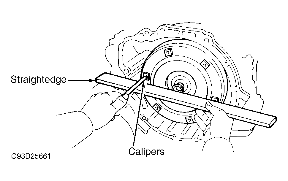
- Install the torque converter on the transaxle. Using a straightedge and calipers, measure the torque converter installed depth. For torque converter installed depth specifications, refer to the TORQUE CONVERTER DEPTH SPECIFICATIONS . Also, refer to Fig 4.
TORQUE CONVERTER DEPTH SPECIFICATIONS
| Application |
In. (mm) |
| Celica |
| A4-GZE |
.898 (22.80) |
| 5S-FE |
.657 (16.70) |
| Corolla |
.906 (23.00) |
| MR2 |
.510 (13.00) |
| Paseo |
.528 (13.40) |
| Prizm |
.787 (20.00) |
 Courtesy of © TOYOTA, LICENSE AGREEMENT TMS1002
 Courtesy of © TOYOTA, LICENSE AGREEMENT TMS1002
 BEARING RACE & THRUST BEARING SPECIFICATIONS
| Application (Letter ID) |
Outer Diameter In. (mm) |
| Front Bearing Race |
| "A" |
1.469 (37.30) |
| "B" |
1.772 (45.00) |
| "C" & "D" |
1.492 (37.90) |
| "E" |
1.693 (43.00) |
| "F" & "G" |
N/A |
| "H" (3) |
1.646 (41.80) |
| Thrust Bearing - A-241E, A-241L & A-243L |
| "A" |
1.480 (37.60) |
| "B" |
1.772 (45.00) |
| "C" & "D" |
1.421 (36.10) |
| "E" |
1.654 (42.00) |
| "F" |
2.272 (57.70) |
| "G" (A-244E) |
1.720 (43.70) |
| "G" (Except A-244E) |
1.780 (45.20) |
| "H" - A-240L |
1.780 (45.20) |
| "H" - A-241E, A-241L & A-243L |
1.720 (43.70) |
| Rear Bearing Race |
| "A" |
1.480 (37.60) |
| "B" |
N/A |
| "C" |
1.378 (35.00) |
| "D" |
1.406 (35.70) |
| "E" |
1.654 (42.00) |
| "F", "G" & "H" |
N/A |