Transaxle Disassembly
- Remove oil cooler pipes, manual shift lever and neutral safety switch. Remove filler tube and dipstick. Remove throttle cable lock plate. Remove solenoid wire lock plate. On A-240L, A-241L and A-243L transaxles, remove governor cover bracket. See Fig 1 and Fig 2
.
- Remove governor cover and "O" ring . Remove governor body, thrust washer, governor body adapter, gasket and governor oil strainer. On A-240E, A-241E and A-244E transaxles, remove lock plate and pull out speed sensor. Remove "O" ring from speed sensor. Remove 2 bolts and sensor cover bracket. Using a screwdriver, remove sensor cover. DO NOT
damage cover. Remove sensor rotor. Remove sensor adapter. See Fig 2.
- On all transaxles, remove oil pan and gasket. Remove magnet(s) from oil pan. Remove tube bracket and oil strainer. Remove manual detent spring. Disconnect solenoid connectors. Remove control valve assembly. See CONTROL VALVE ASSEMBLY under ON-VEHICLE SERVICE. Remove throttle cable from transaxle case. Remove 2nd brake apply gasket. Remove 2nd brake drum seal.
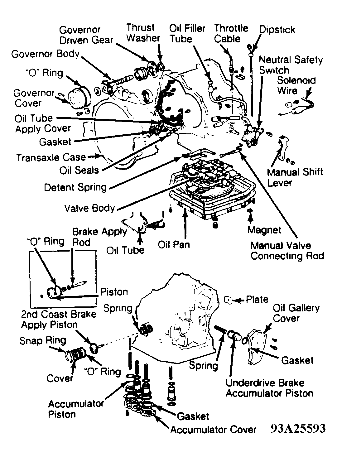 Courtesy of © TOYOTA, LICENSE AGREEMENT TMS1002
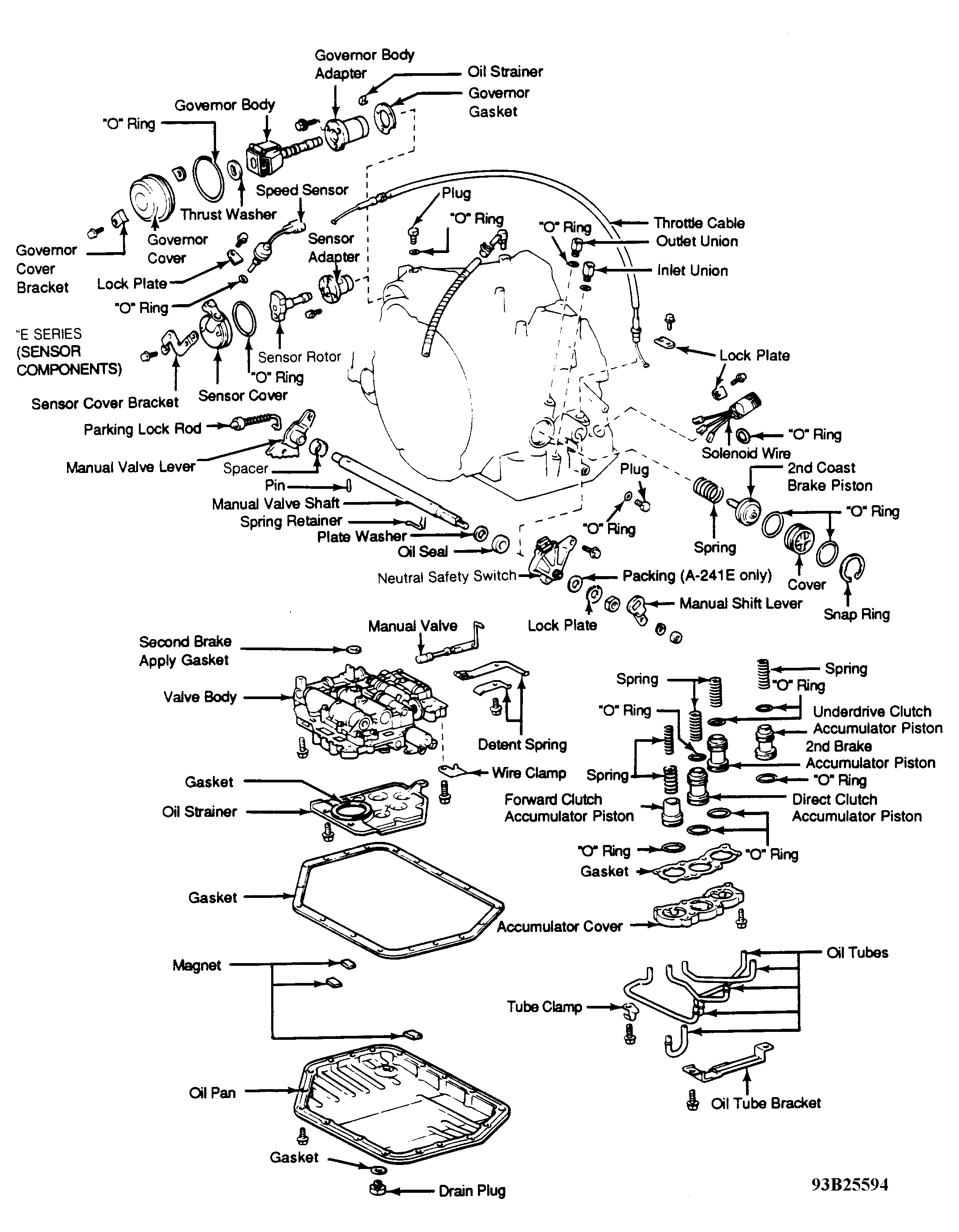 Courtesy of © TOYOTA, LICENSE AGREEMENT TMS1002
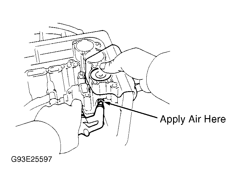
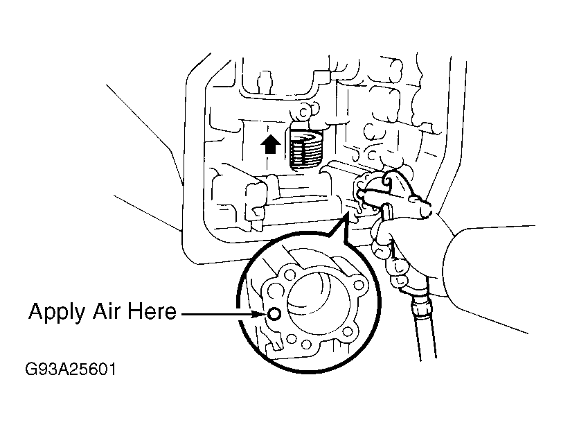
- Apply 14 psi (1 kg/cm2
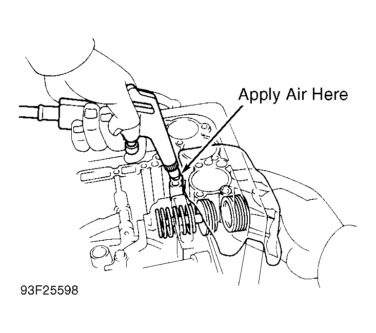
) of compressed air to oil passage to remove underdrive clutch accumulator piston and spring. See Fig 3. Loosen accumulator cover bolts evenly until spring tension is released. Remove cover and gasket. Remove forward clutch accumulator piston and springs. Apply 14 psi (1 kg/cm2
) of compressed air to oil passage to remove direct clutch accumulator piston and spring. See Fig 4.
- Apply 14 psi (1 kg/cm2
) of compressed air to oil passage to remove 2nd brake accumulator piston and spring. See Fig 5. Using Expander (09351-32050), remove 2nd coast brake piston snap ring. Apply 14 psi (1 kg/cm2
) of compressed air to oil passage to remove 2nd coast brake cover. Remove 2nd coast brake piston and spring. See Fig 6.
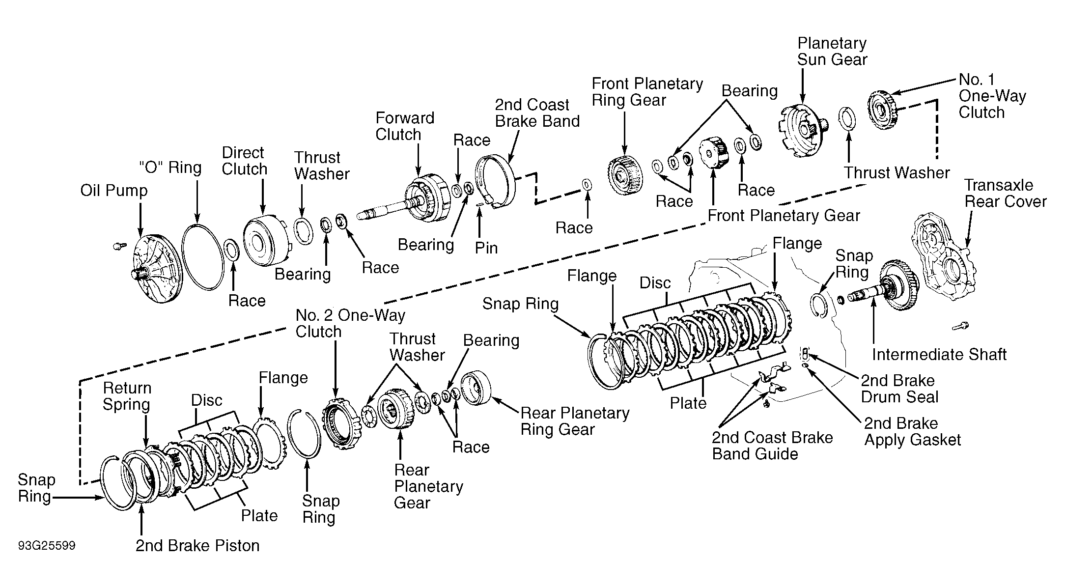
- Remove oil pump retaining bolts. Using Puller (09351-32061), pull oil pump free from transaxle case. Remove oil pump. Remove race from oil pump. Remove direct clutch and forward clutch from transaxle case. Remove direct clutch from forward clutch. Remove thrust washer, bearings and races from forward clutch. See Fig 7.
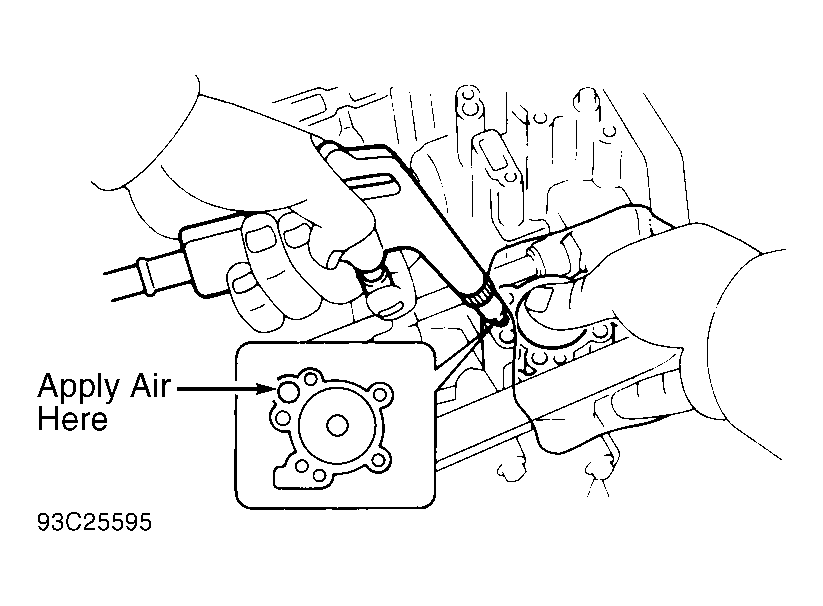 Courtesy of © TOYOTA, LICENSE AGREEMENT TMS1002
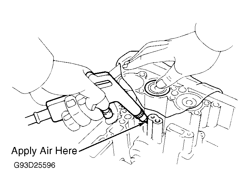 Courtesy of © TOYOTA, LICENSE AGREEMENT TMS1002
 Courtesy of © TOYOTA, LICENSE AGREEMENT TMS1002
 Courtesy of © TOYOTA, LICENSE AGREEMENT TMS1002
 Courtesy of © TOYOTA, LICENSE AGREEMENT TMS1002
- Using small screwdriver, push 2nd coast brake band pin inward and remove pin from oil pump mounting bolt hole. Remove 2nd coast brake band. Remove front planetary ring gear. Remove race and bearing from ring gear. See Fig 7.
- Remove front planetary gear. Remove bearings and races from planetary gear. Remove sun gear, sun gear input drum, thrust washer, 2nd brake hub and No. 1 one-way clutch. Using compressed air, confirm 2nd brake piston operates smoothly. See Fig 8. Remove 2nd coast brake band guide.
- Remove 2nd brake drum retaining snap ring. Remove 2nd brake drum. Remove thrust washer and 2nd brake piston return spring. Remove plates, discs and flange. Note number and location of components. Remove No. 2 one-way clutch retaining snap ring. Remove No. 2 one-way clutch and rear planetary gear. See Fig 7.
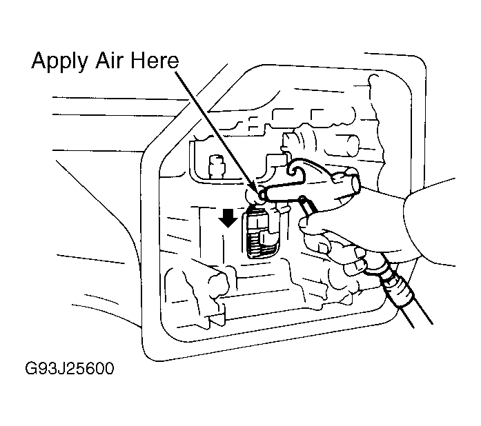
- Remove thrust washers from both sides of planetary gear. Remove rear planetary ring gear with bearing and races. Using compressed air, confirm 1st and reverse brake piston operates smoothly. See Fig 9. Remove flange retaining snap ring. Remove flange, plates and discs. Note number and location of components. Remove rear transaxle cover bolts. Tap rear cover using a plastic hammer. Remove cover. Remove intermediate shaft.
- Remove snap ring. Remove transaxle housing-to-case bolts. Remove transaxle housing. Remove differential assembly, governor driven gear and thrust washer. Remove apply gaskets from transaxle case. See Fig 10. Using chisel, release staked area of countershaft lock nuts. Using Holder (09330-00021) and Adapter (09351-32031), remove front and rear countershaft lock nuts.
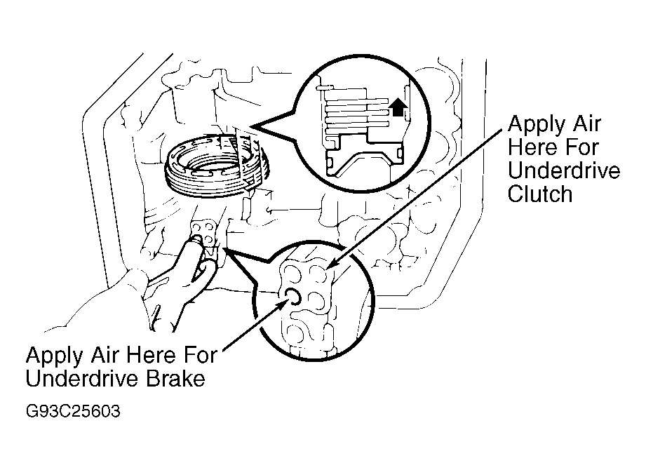
- Using Puller (09351-32061), remove counterdriven gear. Remove thrust needle bearing. Remove countershaft assembly. Remove thrust bearing and race from countershaft. Remove underdrive clutch drum and anti-rattle clip. Using compressed air, confirm underdrive brake piston operates smoothly. See Fig 11. Remove oil seal rings. Using appropriate press and Adapter (09351-32070), carefully remove underdrive brake snap ring.
- Remove flange, plates and discs. Note number and location of components. Remove brake return spring. Using compressed air, remove underdrive brake piston. See Fig 11. Using Compressor (09351-32040), gradually compress spring assembly and remove snap ring.
- Remove return spring assembly. Apply compressed air to oil passage in transaxle case and remove 1st and reverse brake piston. See Fig 9. If piston does not pop out, remove using needle-nose pliers. Remove parking lock pawl stopper plate, torsion spring and spring guide. Remove pawl shaft clamp, shaft and lock pawl. See Fig 10.
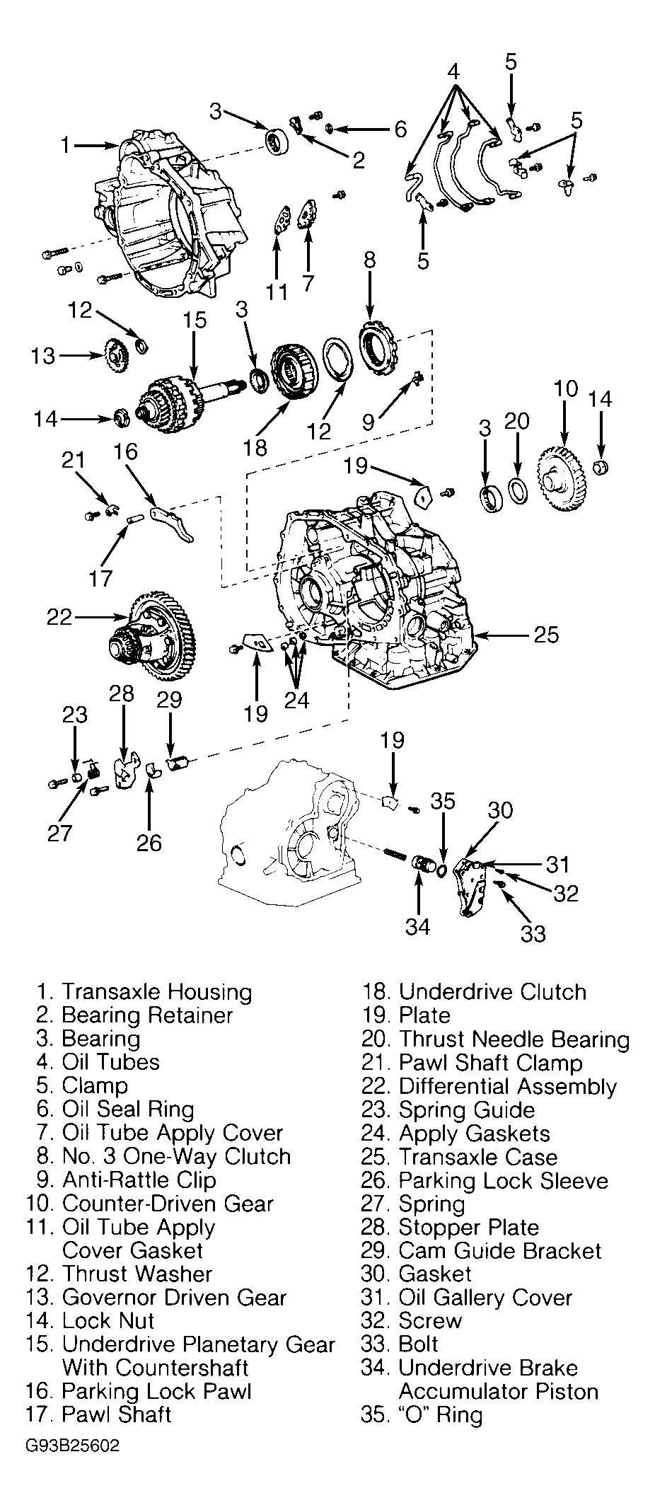
- Remove parking lock sleeve and cam guide bracket. Using a screwdriver and hammer, unstake and remove spacer. Using a punch and hammer, drive out lock pin. Remove spring from manual valve shaft. Remove manual valve shaft, lever and washer. Using screwdriver, remove manual shaft oil seal. See Fig 2. Remove oil gallery cover and gasket. Remove underdrive brake accumulator piston and spring. See Fig 10.
- Using Puller (09308-00010) remove bearing from transaxle case. Remove oil tube clamps. Using screwdriver, carefully remove oil tubes. Remove oil tube apply cover, gasket and strainer. Remove bearing retainer. See Fig 10. Using puller remove bearing from transaxle housing.
 Courtesy of © TOYOTA, LICENSE AGREEMENT TMS1002
 Courtesy of © TOYOTA, LICENSE AGREEMENT TMS1002
 Courtesy of © TOYOTA, LICENSE AGREEMENT TMS1002
 Courtesy of © TOYOTA, LICENSE AGREEMENT TMS1002