Removal Procedure
- Remove the air cleaner assembly. Refer to Air Cleaner Assembly Replacement
.
 Courtesy of GENERAL MOTORS CORP.
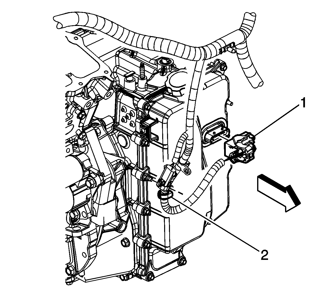
- Remove the wire harness retainer (2) from the control valve body cover stud.
- Disconnect the control valve body transmission control module (TCM) electrical connector (1).
 Courtesy of GENERAL MOTORS CORP.
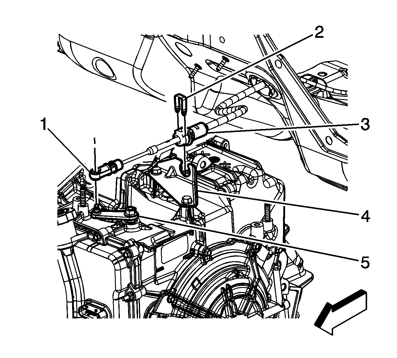
- Disconnect the transmission range selector lever cable terminal (1) from the transmission manual shift lever pin (5).
- Remove the retainer (2) from the transmission range selector lever cable.
- Press the locking tabs inward in order to release the transmission range selector lever cable (3) from the cable bracket (4).
 Courtesy of GENERAL MOTORS CORP.
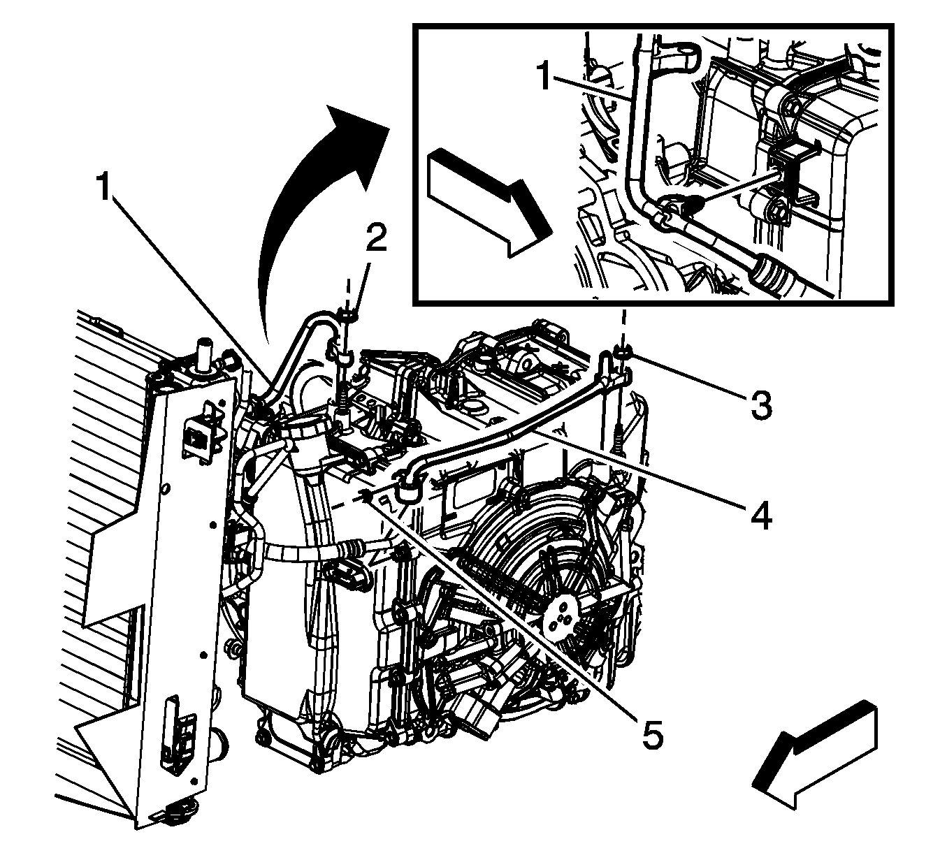
- Release the transmission fluid cooler inlet pipe retainer from the transmission control valve body cover.
- Remove the transmission fluid cooler inlet pipe nut (2).
- Remove the transmission fluid cooler inlet pipe (1) and seal from the transmission.
- Remove the oil cooler outlet pipe retainer nut (5) and retainer from the transmission control valve body cover.
- Remove the transmission fluid cooler outlet pipe nut (3).
- Remove the transmission fluid cooler outlet pipe (4) and seal from the transmission.
- Plug and/or cap both fluid cooler pipes and transmission to prevent contamination.
 Courtesy of GENERAL MOTORS CORP.
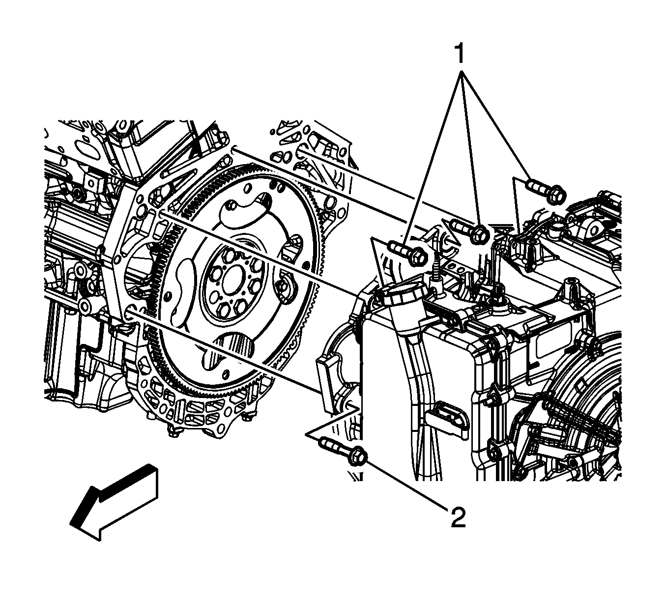
- Remove the upper transmission to engine bolts (1, 2).
- Install the engine support fixture. Refer to ENGINE SUPPORT FIXTURE
.
- Raise and support the vehicle. Refer to ENGINE SUPPORT FIXTURE
.
- Remove the frame. Refer to Front Frame Replacement
.
- Disconnect the left wheel drive shaft from the transmission. Refer to Front Wheel Drive Shaft Replacement
.
- Remove the intermediate drive shaft. Refer to Intermediate Drive Shaft Replacement
.
 Courtesy of GENERAL MOTORS CORP.
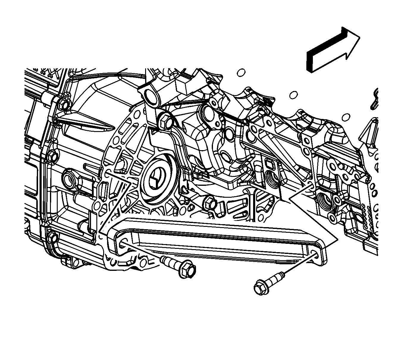
- Remove the transmission brace bolts.
- Remove the transmission brace.
- Remove the left transmission mount bracket from the transmission. Refer to Transmission Mount Bracket Replacement - Left Side .
 Courtesy of GENERAL MOTORS CORP.
- Remove the starter. Refer to Starter Motor Replacement
.
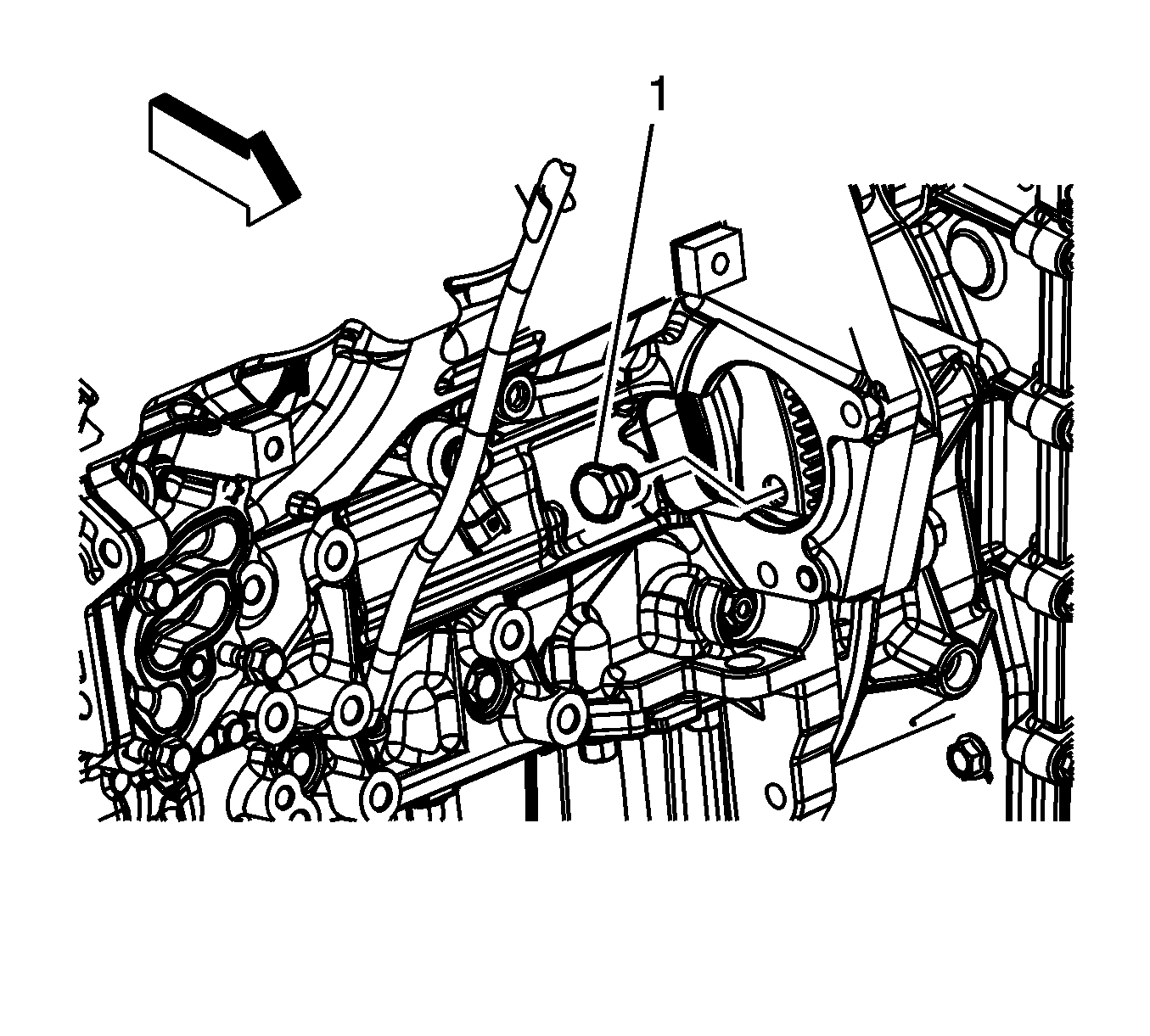
- Mark the relationship of the flywheel to the torque converter for reassembly.
- Remove the 4 torque converter to flywheel bolts (1).
- Use a transmission jack in order to support the transmission.
 Courtesy of GENERAL MOTORS CORP.
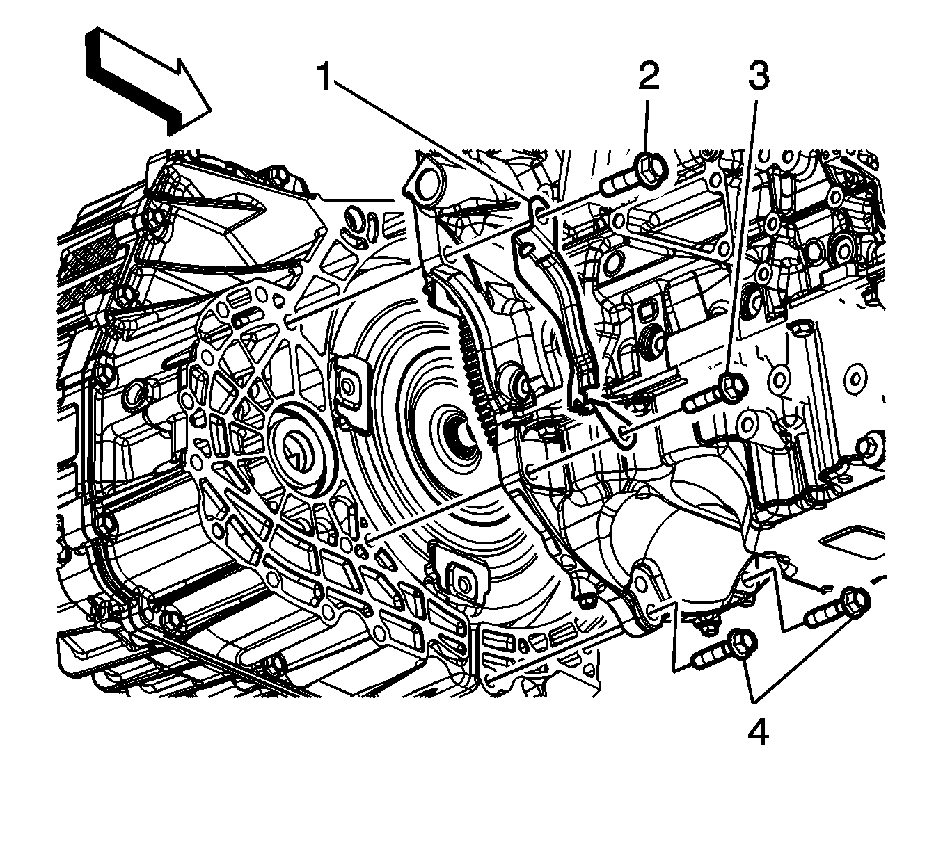
- Remove the flywheel inspection cover bolts (2, 3).
- Remove the flywheel inspection cover (1).
- Remove the remaining transmission bolts (4).
- Separate the transmission from the engine.
- Lower the transmission with the transmission jack far enough to remove the transmission.